Word: This undertaking is solely made for instructional functions and doesn’t encourage unlawful utilization

As seen in James Bond motion pictures; bugging units are utilized by intelligence brokers in several components of the world. These units may help hear conversations from a distance. Their measurement is extraordinarily small which helps it match right into a pocket. They may also be fastened from resort rooms to even the within of a pen.
This undertaking design is a bug system whose vary is upto 1km(or much more). The audio is each transmitted and acquired through frequency modulation. The elements listed within the invoice of supplies desk are wanted for this undertaking.
Invoice Of Supplies

Design
Transmitter
The audio transmitter used right here has a mic and three pins as seen in determine 2. The Vcc and GND pins are related to a 3.3V rechargeable battery that powers the transmitter module. The third pin is to attach the antenna for the transmitting vary to be prolonged.
The case that’s getting used to position the transmitter in, must have tiny holes, such that the mic can seize the sound. On this undertaking we have now used a 3D printed case by designing it accordingly.

Receiver
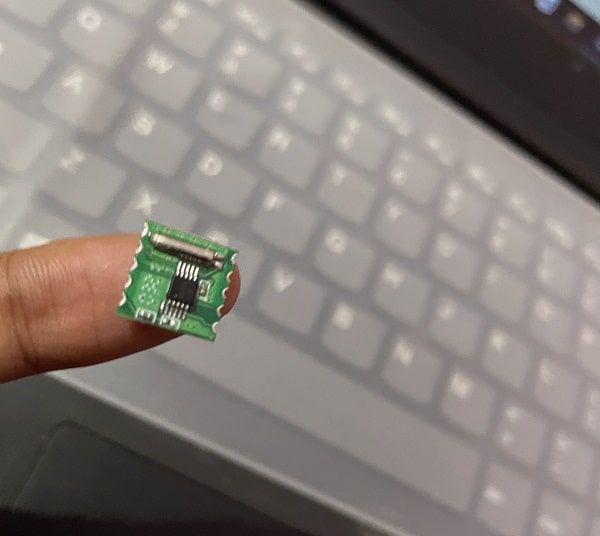
The RDA5807M frequency modulation chip is as tiny as proven in determine 3. An ESP8266 12F chip is required to drive it; as it really works on I2C communication which is identical interface used with the ESP chip. This scans and matches the frequency of the receiver with the transmitted sign. Because the ESP8266 chip doesn’t have USB ports, an FTDI module is required to program it for communication. Utilizing the USART serial port to drive the RDA5807M FM chip we ship the command to ESP which additional sends the sign to the I2C port of the FM chip. To create this system the radio library is used to drive the FM chip and for use over I2C . The ESP board within the Arduino IDE must be put in, after which the library and programming of the ESP chip could be carried out. To know extra about the identical kindly seek advice from the hyperlink.
After putting in the radio library within the Arduino IDE, it’s uploaded and scanned to the ESP chip. The ESP chip must be set within the programming mode by connecting the GPIO 0 to GND and Vcc to 3V of the FTDO module. The GND to GND must be related together with the Tx pin to Rx pin and vice versa earlier than importing the code.


Connections
After the ESP chip is programmed, the modules must be related. From the circuit diagram given in determine 5, it’s seen that the FM audio transmitter module is related to the battery contained in the case as designed within the pic under.


Subsequent the ESP and RDA5807M transmitter chip wires are soldered accordingly. The I2C pins of the RDA5807M chip are soldered with ESP 12F I2C pins. The powering pins are soldered to 3V and Vcc pins of ESP, other than the GND to GND pins. The antenna is now related to the FM ANT pin of RDA5807M. Two microsized audio system are related to the RDA5807M L & R audio pins.


Testing

The audio transmitter FM system is powered on and hidden within the desired location. The ESP and FM radio receiver system are plugged and the serial port is opened. After scanning the vary of FM channels, the channel for the best frequency is chosen. In different phrases, this implies, the FM channel of the audio bugging system is chosen, and now you can hear what’s being talked about on the place the transmitter is positioned.


