 Embedded system undertaking that typically entails a microcontroller unit (MCU) consumer interface (UI) is a typical and inevitable requirement. The easy type of arriving this selection of UI is with the assistance of a monochrome LCD, which serves as a primary output machine and a matrix keypad interface for accepting inputs from the consumer. In truth, majority of the UI designs are with 2×16 LCD ASCII compliant show, usually JHD162A together with both 4×4 or 4×3 matrix keypads.
Right here, we begin with the event of a tool driver for a matrix keypad, usually written in embedded-C for microcontroller. We’ll think about an 8-bit AT89S52 MCU (works effectively for any C51 MCU), which is well obtainable and whose structure is acquainted to many people. We’ll implement a C driver for scanning a key within the polled mode first and see how one can take a look at it with out implementing or coupling the output driver (LCD).
We will then examine the design elements of changing this driver by binding/locking it into an asynchronous exterior interrupt pin (/INT0 pin) and current the implementation and testing elements concerned in reaching driver in embedded C. It’s suggested to think about additional elements with Keil µVision 5 IDE with C51 cross-compiler (that assist legacy C51 microcontroller households) put in in Home windows 10 host PC together with simulation software program similar to Proteus 7.7 or above for validation.
The undertaking has 4 components the place the supply program (Project1 by way of Project4) of every half is written in embedded C programming language. The hex code generated by way of Keil µVision 5 IDE is used for simulation and verification utilizing Proteus software program.
Earlier than we dig into the technicality, we have to perceive the necessity for this conversion. Since majority of the embedded tasks take care of this customary polled-loop driver for keypad, the necessity to convert arises in following circumstances:
(a) When the MCU is anticipated to deal with the visitors over serial (usually UART) port for reaching networking. Allow us to think about an instance of dealing with the information utilizing GSM’s ASCII terminal instructions (AT) within the type of SMS. Whereas the MCU is busy in dealing with this SMS visitors utilizing handshaking choices, if consumer presses any enter, forcing the microcontroller’s consideration, the normal method of polled-loop driver fails to recognise the consumer inputs. This requirement causes a significant issue when the consumer is trying to configure the information and visitors is flooding over networking (on this case serial) interface.
(b) If the MCU is busy in performing the sensor knowledge processing, both utilizing the off-chip ADC interface possibility or on-chip ADC register polling, and the consumer is triggering an enter utilizing the enter machine. On this case additionally, the consumer consideration shall be unanswered because the MCU is already busy in sensory job.
Polled mode 4×3 embedded C driver and its validation for C51 MCU
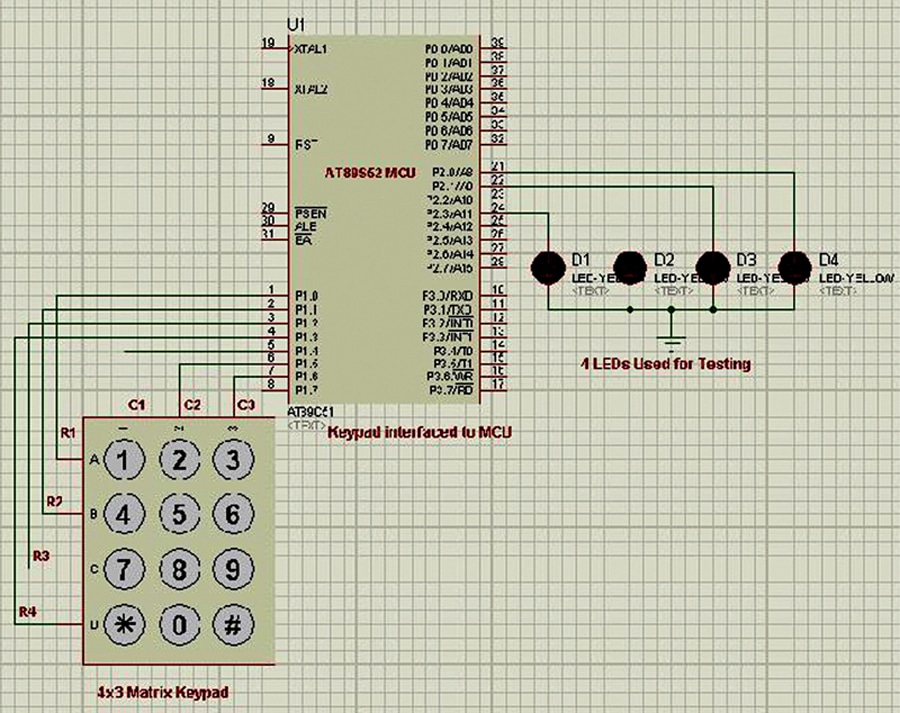
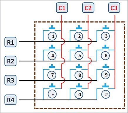
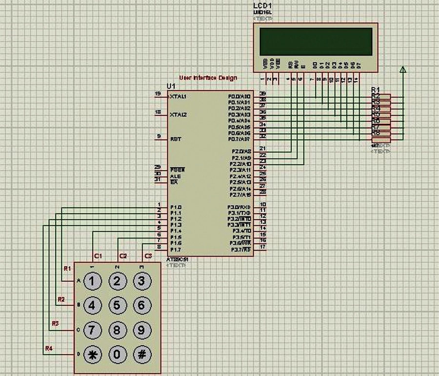
Allow us to think about the 4×3 matrix keypad with 4 rows and three columns being linked to Port 1 of AT89S52 MCU, as proven in Fig. 1. That is principally the connections in Proteus simulation software program. The 4 LEDs are used just for testing and are linked to P2.0 by way of P2.3. A typical keypad format diagram is proven in Fig. 2. The polled-loop key-scanning algorithm could be very easy and easy, as proven in steps 1 by way of 7 given beneath:
Step-1: Configure the columns as inputs (logic-1) and rows as outputs (logic-0)
Step-2: Begin polling the KeyScan by in search of any change in column (1 to 0)
Step-3: Is there any change in columns (i.e., C1=0 or C2=0 or C3=0)
If sure,
then, go to Step – 4.
else
Go to Step-2.
Step-4: Make R1=0 and preserve R2=R3=R4=1 and,
If C1=0 then,
pressed secret is – ‘1’ and return.
else if C2=0 then,
pressed secret is – ‘2’ and return.
else if C3=0 then,
pressed secret is – ‘3’ and return.
else
go to step – 5:
Step-5: Make R2=0 and preserve R1=R3=R4=1 and,
If C1=0 then,
pressed secret is – ‘4’ and return.
else if C2=0 then,
pressed secret is – ‘5’ and return.
else if C3=0 then,
pressed secret is – ‘6’ and return.
else
go to step – 6:
Step-6: Make R3=0 and preserve R1=R2=R4=1 and,
If C1=0 then,
pressed secret is – ‘7’ and return.
else if C2=0 then,
pressed secret is – ‘8’ and return.
else if C3=0 then,
pressed secret is – ‘9’ and return.
else
go to step – 7
Step-7: Make R4=0 and preserve R1=R2=R3=1 and,
If C1=0 then,
pressed secret is – ‘*’ and return.
else if C2=0 then,
pressed secret is – ‘0’ and return.
else if C3=0 then,
pressed secret is – ‘#’ and return.
else
go to step – 2
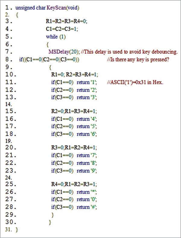
The implementation of this primary half (Project1) in embedded C perform is proven in Fig. 3. Upon any key press, the ASCII equal of the pressed secret is recognized and is returned. Therefore, within the testing of the circuit given in Fig. 1, the decrease nibble alone is ample because the LEDs point out the pressed digit.
For example, if the consumer presses key-‘1’, the ASCII of ‘1’, which is 0x31, i.e., 0110 0001, is proven on the LEDs. In the identical manner, all of the keys of the keypad could also be examined by observing their equal binary outputs on LEDs.
Allow us to now have a look at the method of changing the above polled-loop driver by binding the interrupt and reveal the method of context switching from the applying to interrupt service routine (ISR), and vice-versa.
Circuit diagram for interrupt-driven keypad
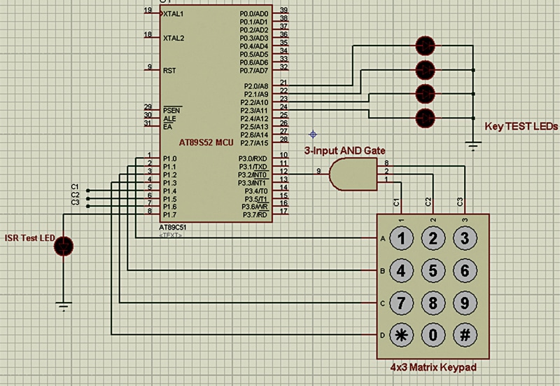
There are two exterior interrupt pins /INT0 and /INT1 of AT89S52, which can be found as alternate-pin features of the P3.2 and P3.3 GPIOs, respectively. Amongst these, allow us to think about utilization of /INT0 pin, the P3.2 pin. A 3-input AND gate 4073 IC is used such that its output should be linked to /INT0 (P3.2), whereas the inputs are linked to the three columns C1, C2, and C3, as proven in Fig. 4.
Implementation of interrupt-driven driver
For reaching the important thing enter, because the columns had been locked to interrupt pin, any key pressed will consequence right into a change of column sign and thereby generate an interrupt at /INT0 pin. We should allow the interrupt /INT0 pin by configuring the IE register. Furthermore, we should configure it as an edge-triggered kind of interrupt utilizing TCON register in most important utility.
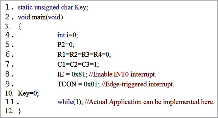
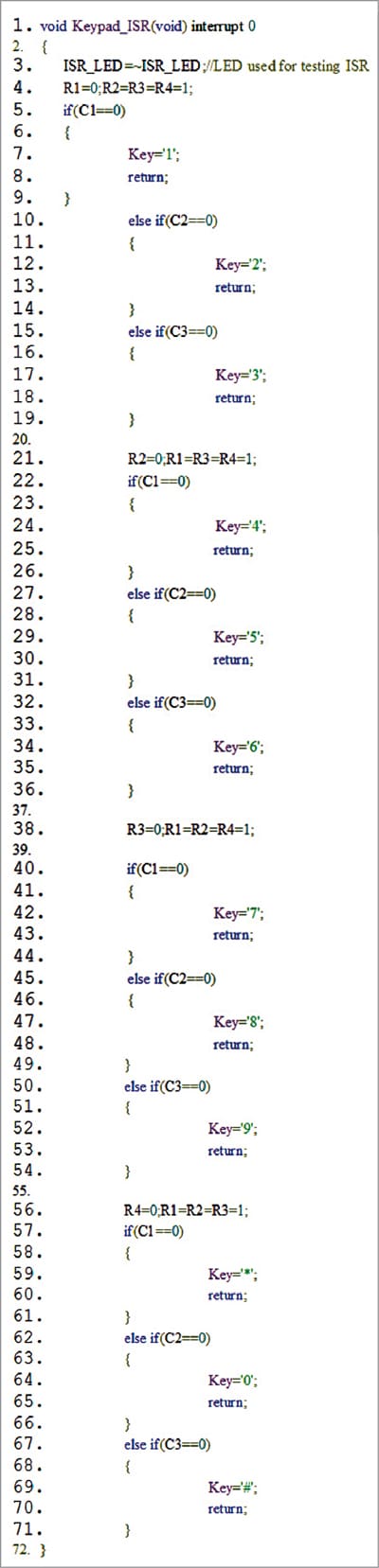
The essential configuration within the code for Project3 is proven in Fig. 5. The MCU’s C-ISR perform ‘Keypad_ISR’ is carried out as indicated in Fig. 6.
Some crucial observations of the carried out ISR are:
- The interrupt should be configured as edge triggered. That is achieved in AT89S52 by configuring TCON register. In any other case, even for a single press the interrupt will carry on operating as if a number of occasions are occurring.
- An interrupt service routine perform should not return any worth. Therefore, we use the idea of world shared useful resource, which in our case would be the international variable. Within the implementation, the variable ‘Key’ shall be appearing as a shared useful resource. Discover that this shared useful resource is accessible not solely in the primary but additionally within the ISR.
- Within the implementation given right here an LED is deliberately linked to the unused GPIO P1.7 pin of AT89S52, which can toggle upon the important thing press as a result of line-3 of Fig. 6.
- Each time a secret is pressed by the consumer, the corresponding column standing within the keypad shall be modified to 1. Consequently, the interrupt shall be triggered, and the applying shall be paused because it enters into /INT0 ISR. This course of is known as {hardware} context switching. Discover that in this time, the system stack shall be used. (Financial institution-1 in RAM)
- Contained in the ISR, the precise checking or figuring out the precise row’s key, which is accountable for the important thing press, is detected and the confirmed secret is stored within the shared useful resource variable ‘Key’ and the ISR ends by forcing it to return. The suspended utility will now be prepared by context retrieval utilizing stack’s POP operations.
- The pseudo-code proven in Fig. 7 is proposed for detecting a legitimate key pressed in most important code for additional utility improvement.
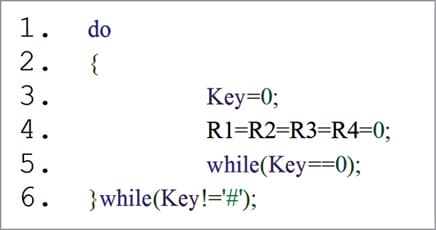
Fig. 7: Pseudo-code supply itemizing for detecting a keypress in most important utility - One other necessary inference is that there shall be no key debouncing drawback, not like in polled-loop keypad. Consequently, the intentional delay for each consecutive key press shouldn’t be mandatory.
By contemplating this method of interrupt-based keypad driver, one can implement and obtain the real-time response for UI with out porting the RTOS into the MCU. It’s because the ISR will run regardless of what the applying is doing, forcing the CPU’s consideration. Subsequently, in consequence if the design is finished with this beneficial UI, other than reaching the real-time response, the reminiscence footprint (each Flash and RAM) can also be enormously decreased.
After downloading the supply applications from EFY web site, utilizing circuit proven in Fig.8 together with Project2, the polled-loop utility is examined with any 4-digit enter as consumer ID and ‘1982’ as password. The ISR-locked keypad driver is examined utilizing Fig.4 and Project3. Lastly, the identical utility with LCD is examined utilizing Fig. 9 and Project4.

Obtain Supply Code
N. Abid Ali Khan is Assistant Professor within the Division of ECE at Vasavi School of Engineering (Autonomous), Hyderabad. He has been engaged on power-efficient embedded networking architectures and is captivated with microcontrollers, ARM, RTOS, embedded programs, and programming
