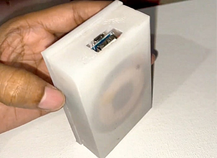
 MagSafe, a magnetic expertise embedded into the interior engineering of iPhone 12 mannequin, was initially created as a security function for MacBook charging cords. It creates a brand new ecosystem of equipment for simple attachment and sooner wi-fi charging. The price of a wi-fi energy financial institution with MagSafe ranges from ₹5000 to ₹7000. Aside from being costly, it’s tough to obtain from the market.
| Invoice Of Materials | ||
| Part identify | Amount | Description |
| Inductor coil | 1 | For wi-fi energy |
| 5V stepup charging BMS | 3 | 5V stepup charging module |
| Wi-fi energy TX module | 1 | Energy transmitter |
| 3.3V rechargeable battery | 2 | 2000mAh or 1000mAh |
| 3D printed case | 1 | Powerbank case |
This DIY mission is of a wi-fi energy financial institution with MagSafe, which cannot solely cost iPhones but in addition different suitable gadgets (together with IoT gadgets). It gives the good thing about having a wi-fi powering system, MagSafe expertise, and a USB charging system that’s suitable with many gadgets.
Designing
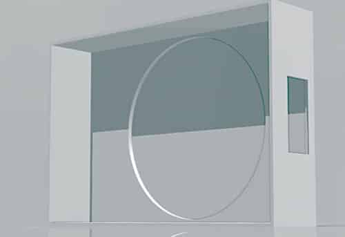
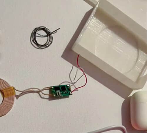
The scale of the battery is essential for designing a correct case. Each the battery and the charging module have to suit contained in the case, which needs to be lower to make provision for enter energy charging (USB) and output energy. A cavity can be made on one wall of the case for the coil and MagSafe magnet to be positioned, as proven in Fig. 3.
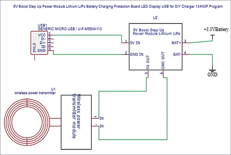
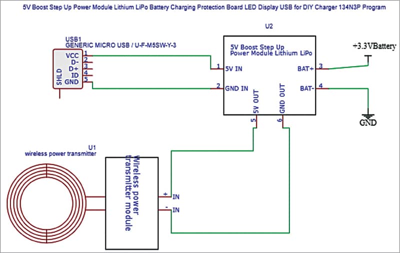
For the circuit, we are able to both use a 5V step-up battery administration IC or a module. A TP4056 one-ampere battery charging module was used within the writer’s prototype. The module’s output is linked to a wi-fi transmitter, as proven in Fig. 5.
Connections
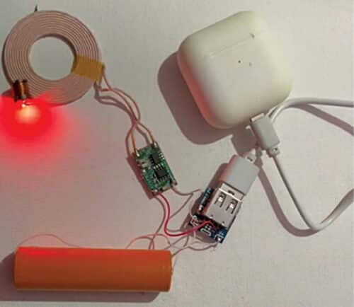
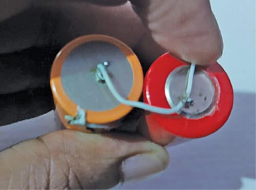
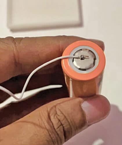
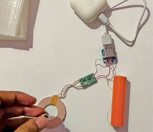
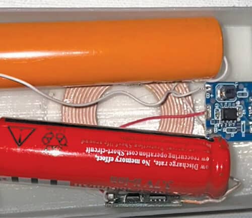
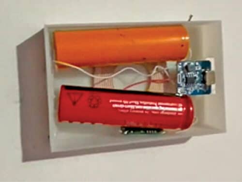
The battery terminals are soldered both with the wires straight or a battery pack connector strip. In case of a number of batteries getting used, be sure to attach the batteries in parallel (see Fig. 6). Subsequent, join the battery step-up charging module as proven within the circuit diagram. The wi-fi charging coil ought to now be soldered with the enter of the wi-fi energy transmitter module and its output with the charging module output pins (see Fig. 7 by means of Fig. 10).
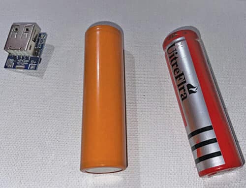
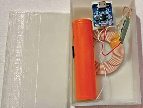
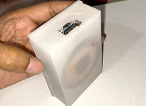
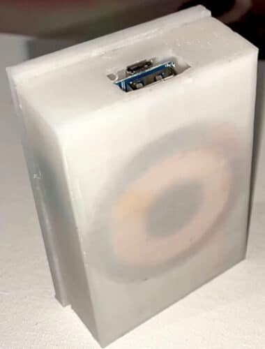
The coil could now be mounted within the cavity with a magnet for MagSafe. Above this repair the battery together with the BMS module in USB cavity of the 3D-printed case. Lastly, repair the highest cowl (see Fig. 11 by means of Fig. 14). For MagSafe, repair the round magnet in cavity with glue.

Testing
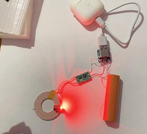
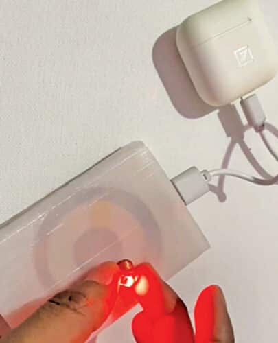
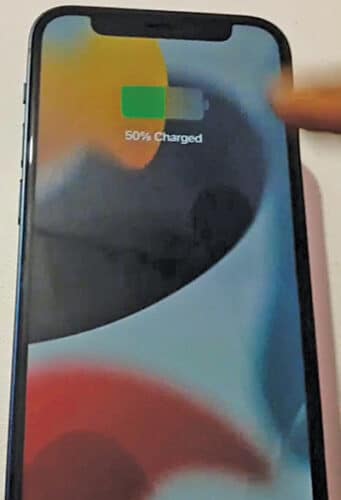
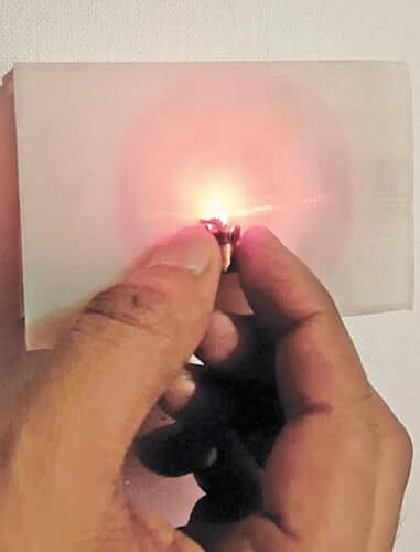
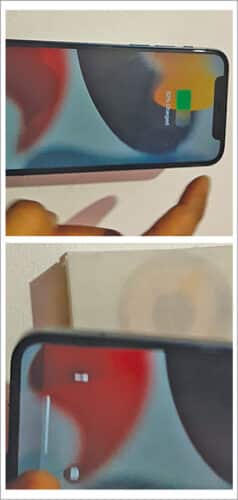
To check the circuit, plug in any machine to the USB and see it charging. (Within the footage an Airpod case is proven plugged in.) Subsequent, convey any wi-fi machine (a wi-fi LED is proven within the footage) and see the LED glowing, as proven in Fig. 19, as the facility financial institution emits energy within the type of electromagnetic waves. A cellphone may be charged by putting it on the machine, as proven in Fig. 20.
Ashwini Kumar Sinha is a expertise fanatic at EFY

