 There are numerous sorts of dwelling and industrial automation techniques out there out there. These embrace IR distant controller, Bluetooth dwelling automation, DTMF dwelling automation, Wi-Fi dwelling automation, RF dwelling automation, and voice managed dwelling automation. The one offered here’s a low-cost automation system. It may be used at dwelling or in an industrial atmosphere to modify units on and off.
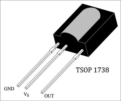
IR distant controllers and receivers comply with commonplace protocols for sending and receiving the information. Among the commonplace protocols are NEC, PHILIPS RC5, JVC, and SIRC (Sony infrared distant management). We can be utilizing the NEC protocol for this undertaking. After understanding the body format of IR distant, we are going to interface IR receiver TSOP1738 with PIC16F676 microcontroller to decode the important thing pressed from an NEC IR distant, as proven in Fig. 1.

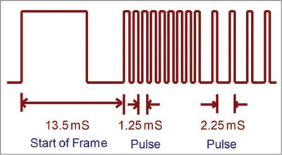
Every bit is transmitted utilizing the heartbeat distance, as proven in Fig. 2. Logical ‘0’ is a 562.5µs pulse burst adopted by a 562.5µs area, with a complete transmit time of 1.125ms. Logical ‘1’ is a 562.5µs pulse burst adopted by a 1.6875ms area, with a complete transmit time of two.25ms.
When a secret’s pressed on the distant controller, the message transmitted consists of the next within the order under:
- A 9ms main pulse burst (16 instances the heartbeat burst size used for a logical knowledge bit)
- A 4.5ms area
- The 8-bit handle for the receiving system
- The 8-bit logical inverse of the handle
- The 8-bit command
- The 8-bit logical inverse of the command
- A remaining 562.5µs pulse burst to suggest the tip of message transmission
The 4 bytes of knowledge bits every are despatched with least vital bit first. Fig. 3 illustrates the format of an NEC IR transmission body for an handle of 00h (00000000b) and a command of ADh (10101101b).
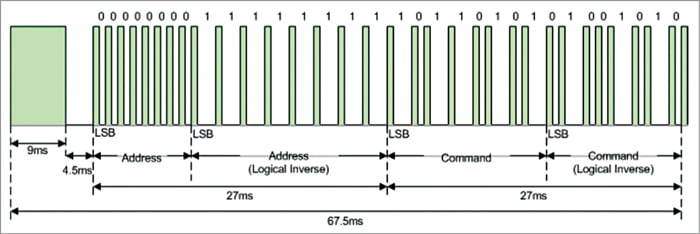
A complete of 67.5ms is required to transmit a message body. It wants 27ms to transmit the 16 bits of handle (handle+inverse) and the 16 bits of command (command+ inverse).
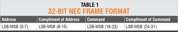
Desk 1 reveals 32-bit NEC body format and Desk 2 reveals the entire checklist of IR key codes for the NEC IR distant.
 PIC16F676 controller
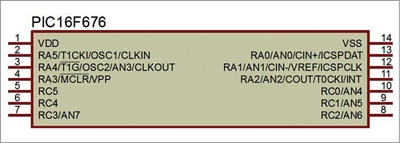
PIC16F676 is Microchip’s 8-bit CMOS PIC microcontroller with flash reminiscence. It is available in a 14-pin package deal with high-performance RISC CPU, which makes it an excellent alternative for many digital functions associated to embedded techniques or industrial automation. This tiny chip incorporates every thing it’s good to develop particular person initiatives. A few of its options are:
- The flash reminiscence of high-performance PIC16F676 helps in rising the processing pace of the microcontroller.
- It is available in PDIP, SOIC, and TSOP packages, all of which can be found in 14-pin configuration.
- PIC16F676 accommodates program reminiscence with reminiscence area round 1.7kB, whereas RAM and EEPROM recollections are of 64 bytes and 128 bytes, respectively.
- One 10-bit ADC module within the system comes with eight analogue channels. This module performs a significant function for sensor interfacing and changing analogue values to digital.
- Energy-on reset, comparator, in-circuit serial programming, and grasp clear reset are another options integrated within the system. These assist it keep forward of the opposite onboard chips and removes the necessity of shopping for exterior parts for finishing up totally different operations. Pin diagram of PIC16F676 is proven in Fig. 4.
Circuit and dealing
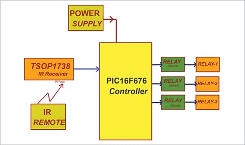
The undertaking makes use of PIC16F676 microcontroller and an NEC IR distant to modify on/off any AC load, together with lights and followers, from the consolation of your chair or mattress. The totally different IR indicators from the distant for the totally different lights and followers are acquired by the microcontroller, which then controls the respective relays by way of a relay driver circuit. These relays are used to modify the lights and followers on or off.
 There are numerous sorts of IR distant controllers out there for various units, however most of them work round 38kHz frequency. This undertaking requires an odd IR TV distant. For detecting the IR indicators, TSOP 1738 IR receiver proven in
Fig. 5 is used. It could actually sense the 38kHz frequency sign.
The block diagram of the undertaking is proven in Fig. 6.
On this undertaking the digital IO pins RC0, RC1, and RC2 of Port C of PIC16F676 microcontroller are used to manage the relays to modify the home equipment on/off. These pins are configured as output pins in this system. The IR receiver is linked to pin RC4 of PIC16F676, which is configured as enter pin in this system.
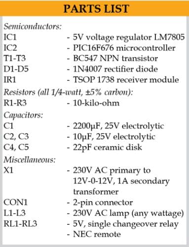
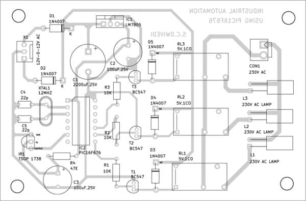
The PIC16F676 microcontroller operates at +5V. Therefore, a transformer is used to step down the 230V AC mains provide, which is rectified utilizing a full-wave rectifier. The rectified voltage is regulated to +5V by utilizing regulator IC 7805. The whole circuit diagram is proven in Fig. 7.
The working of this undertaking is pretty easy. When a button is pressed on the IR distant, it sends a sequence of codes within the type of encoded pulses utilizing 38kHz modulating frequency. These pulses are acquired by the TSOP 1738 sensor after which learn by the microcontroller. The microcontroller decodes the acquired practice of the pulses right into a hex worth and compares it with the predefined hex values in this system.
Every time a secret’s pressed on the IR distant, the transmitted IR sign is acquired by an IR receiver and the secret is decoded by the software program. On this undertaking, your complete 32-bit string (4 bytes of NEC protocol) is used for decoding. On this 32-bit string, the third byte is in contrast in this system for controlling the lights/followers. If any match happens, the controller performs a relative operation by triggering the respective relay by means of transistor BC547 and the corresponding result’s indicated by an on-board LED. The three LEDs within the circuit present the standing of the relays.
On this undertaking, key numbers 2, 4, and 6 of the IR distant have been used for controlling the three relays. Key 2 toggles relay RL1, key 4 toggles relay RL2, and key 6 toggles relay RL3.
Software program
The circuit makes use of the software program program loaded into the interior reminiscence of PIC16F676. This system is compiled utilizing Mikro C PRO model 7.2.0 for PIC compiler and uploaded into PIC16F676. The software program important.c is written in embedded C language, which permits writing the code inside just a few strains. The generated hex code is burnt into the MCU chip utilizing PIC K150 programmer board.
No header, interrupt, or seize and examine mode is used right here to detect IR sign. Digital pin RC4 reads the information, identical to we learn a push button. Every time sign goes excessive or low, debouncing is adopted and the timer is run. Every time the pin adjustments its state to a different, the time values are saved in an array.
IR distant sends logic 0 as 562.5µs pulse and logic 1 as 2250µs pulse. Every time timer detects 562.5µs pulse, this system assumes it to be 0, and when it detects 2250µs pulse, it assumes it to be 1. Then this system converts it into hex. The incoming sign from distant accommodates 32 bits (4 bytes). Program shops all of the bytes within the array after which decodes the third byte to make use of for comparability.
The easy programming assertion ‘change’ case is used to detect and management the house home equipment.
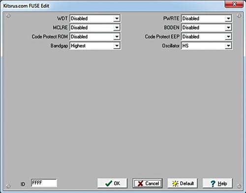
Don’t forget to set fuse bits earlier than programming PIC16F676 utilizing PIC K150 programmer. This system is not going to work with out setting the fuse bits. The fuse bit settings are proven in Fig. 8.
Development and testing
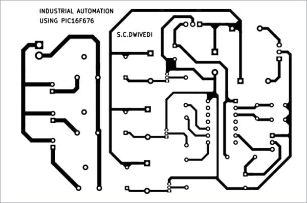
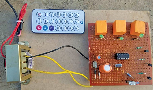
An actual-size PCB structure for the automation system is proven in Fig. 9 and its element structure in Fig. 10. After assembling the circuit on PCB, enclose it in an acceptable field. Receiver IR1 needs to be fastened on the entrance panel, in order that the distant can deal with it to activate any load linked to the respective relay. CON1 needs to be fastened on again facet of the cupboard. All of the three 230V AC home equipment are linked to the circuit utilizing two wires and positioned at their location. The creator’s prototype wired on a general-purpose PCB is proven in Fig. 11.
Obtain PCB and Part Format PDFs: click on right here
Obtain Supply Code
Pamarthi Kanakaraja is an assistant professor (R&D cell) at Okay.L. College, Vaddeswaram, Guntur district, Andhra Pradesh
