The maker toolkit has a core collection of important maker instruments. The instruments that we are able to’t do any work with out. Breadboards, soldering irons, LEDs are necessary, however resistors are the tiny parts that initiatives depend upon.
It doesn’t matter what bord we select, be it Raspberry Pi, Raspberry Pi Pico or Arduino, we’d like resistors to guard our LEDs, divide voltages and supply exact values for our circuits. However what do they do, why do we’d like them and the way can we be certain we have now the right worth? For that we have to do some math, and seek the advice of a couple of datasheets.
On this reference we’ll clarify what resistors are, what they do and let you know the right way to decide the right resistor on your subsequent mission.
What are Resistors?
Resistors are parts which introduce electrical resistance in a circuit. Usually they’re used to cut back the present stream in a circuit, for instance when used with LEDs they cease the LED from consuming an excessive amount of present.
An LED with no resistor will burn itself out in a short time. Resistors will also be used to create voltage potential dividers, helpful circuits that may scale back the voltage in a circuit. Each maker may have some resistors of their kits. They arrive in bandolier strips and could be purchased in singular packs or of their 1000’s.
Why Do We Want Resistors?
Probably the most fundamental use of resistors is to cease a element from consuming an excessive amount of present. Take for instance an LED (Mild Emitting Diode). LEDs are designed to go present in a single path and produce a small quantity of sunshine as they function. If we give LEDs as a lot present as they need, the LED will gentle brightly however quickly burn out. In some instances we can provide it an excessive amount of present without delay, inflicting the LED to “pop” after which die.
We will use the next calculation to find out the precise resistor worth.
R is the resistor worth, Vs is the availability voltage, Vf is the ahead voltage (the quantity element wants), and If is the ahead present.
Let’s put this into observe. We have now a blue LED linked to a 5V provide. The ahead voltage of the LED is 3.2V and the required present is round 10mA. So the calculation seems to be like this.

Because of this the worth of R is 180 Ohms. In the usual collection of resistors we are able to use this precise worth or we are able to select a 150 or 220 Ohm resistor as an alternative. For fundamental duties, the precise worth isn’t important however when designing circuits for skilled / industrial or excessive precision units you have to to make use of the precise values. The precise values could be discovered within the parts datasheet or on the product web page out of your chosen retailer.
For many hobbyist / maker purposes we are able to select the closest worth that we have now. We regularly favor a 220 / 330 Ohm resistor for our LEDs.
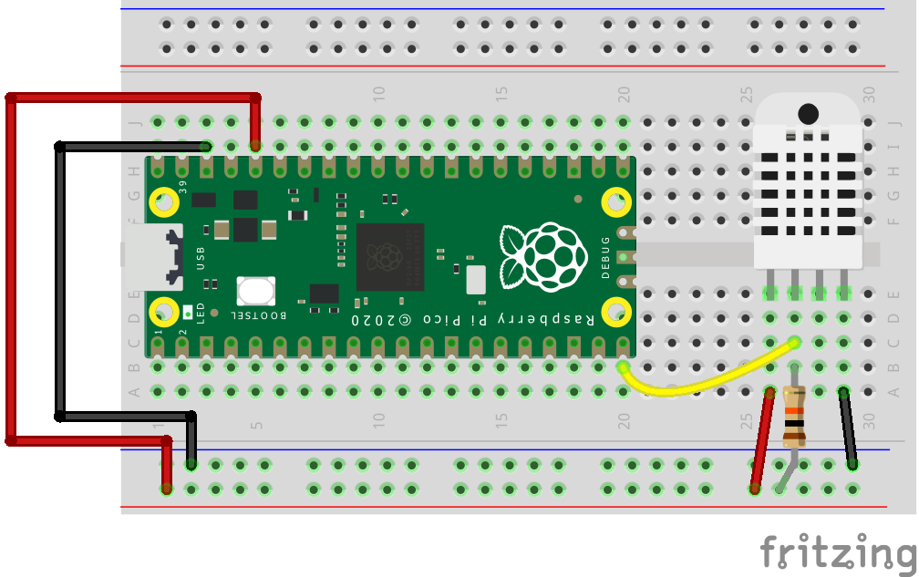
Resistors will also be used to drag up or pull down a GPIO pin. A pull up resistor will pull a pin excessive by connecting a voltage provide to a pin. A pull down resistor will pull a pin all the way down to GND. We used a 10K Ohm resistor with a DHT22 temperature sensor to drag the info pin excessive utilizing the three.3V provide.
Resistors will also be used to drop voltages from one degree to a different. That is referred to as a voltage divider and it’s generally utilized in potentiometers to fluctuate the voltage.
To create a voltage divider we have to use this equation.

Vout is the voltage that we would like.
Vin is the enter voltage.
R1 is the primary resistor’s worth.
R2 is the second resistor’s worth.
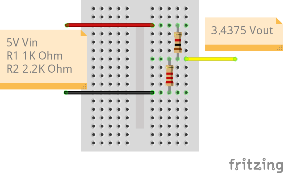
So, for our voltage divider we need to convert the 5V enter voltage to round 3.3V. This course of is often used when we have to change the logic voltage of a element, for instance the HC-SR04. The HC-SR04 ultrasonic distance sensor initially used 5V logic, and so the echo pin, which prompts when sound bounces off an object, will ship 5V to the GPIO.
For an Arduino, that is okay. For a Raspberry Pi, it could injury the pin, and even the Pi. We’re utilizing two resistors, R1 a 1K Ohm resistor (prime) and R2 a 2.2K Ohm resistor (backside) to create a voltage divider. The legs of R1 and R2 go into the identical row of the breadboard. Into R1 we provide 5V and into R2 we hook up with GND. The place the legs of R1 and R2 meet is the output voltage, which must be 3.4375V, properly inside the tolerance of the three.3V GPIO.

The calculation works by including R1 and R2 collectively (1000 + 2200 = 3200) then we divide the worth of R2 by this (2200 / 3200 = 0.6875) and lastly we multiply by the enter voltage (5 8 0.6875 = 3.4375V).
How Do I Select the Right Resistor?
Resistors have coloration bands round their axis. These bands are a code system that we are able to use to establish the worth of a resistor. There are 4, 5 and 6 bands however the most typical are 4. Actually the 4 band resistors are the simplest to learn.
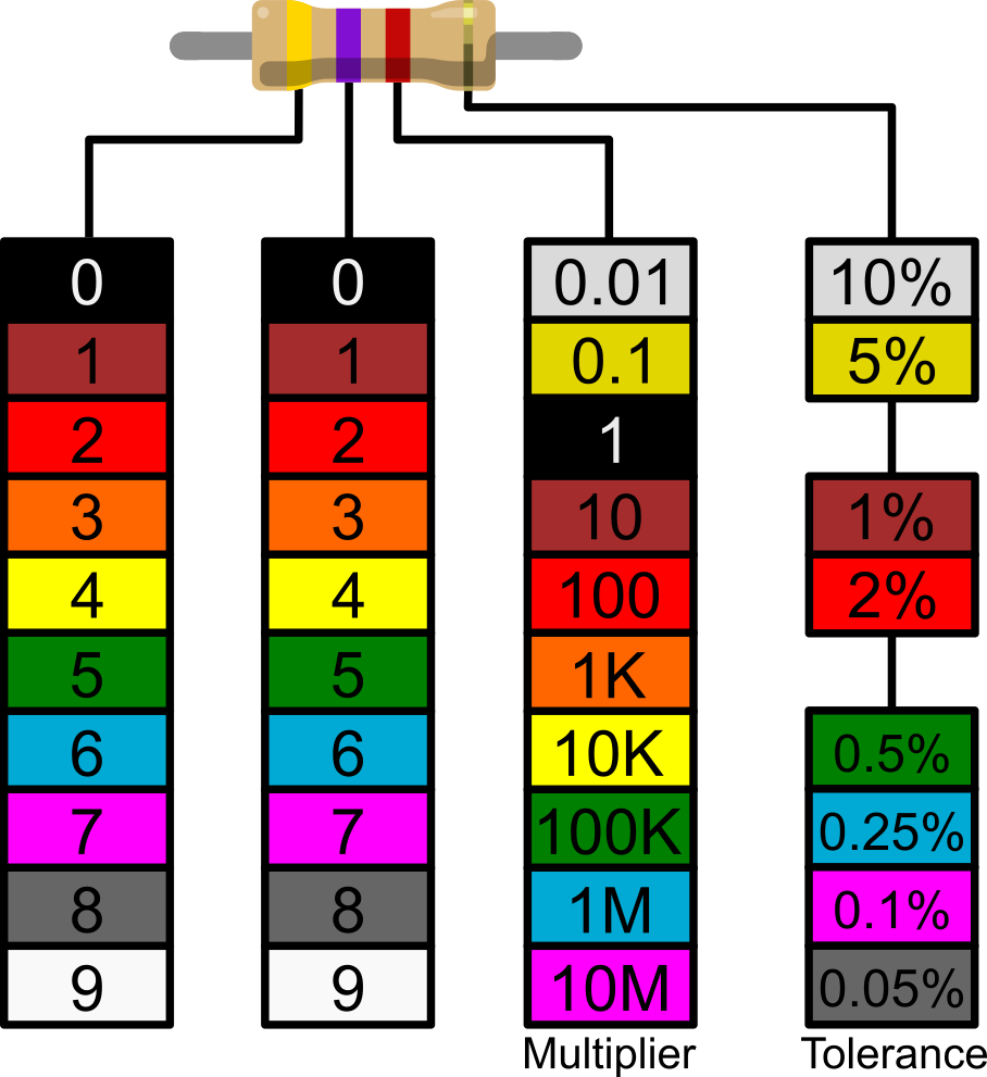
Let’s take this resistor for instance. The bands are printed to the resistor however the ultimate band, tolerance, is printed on one of many “bulges” on the finish of the resistor. We will see the primary band is yellow and the second is violet. This provides us a price of 47. The third band is the multiplier, on this case purple is 100. If we do the mathematics, 47 x 100 = 4700. We have now a 4700 Ohm resistor, typically known as a 4.7K Ohm resistor. The ultimate band is the tolerance. Our tolerance band is gold which implies we have now a 5% tolerance, it could possibly be 5% over or below the 4.7K Ohm worth.
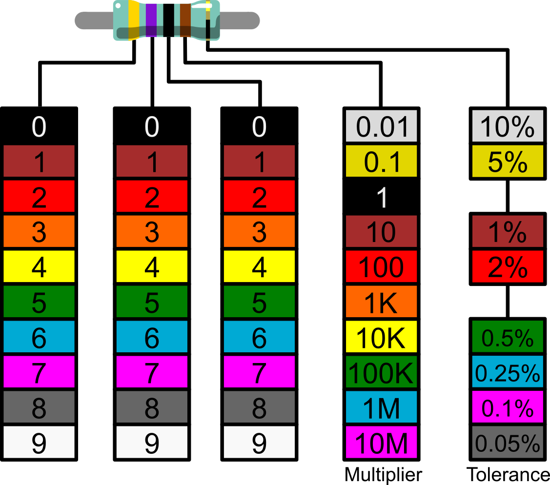
5 band resistors supply further precision and use an additional third digit to dial within the precision. The identical 4.7K Ohm resistor’s third band is now black, which refers to zero. The fourth band is the multiplier and the fifth is our tolerance.
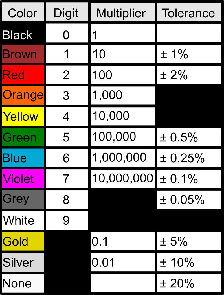
This desk offers a fast reference which could be utilized to 4 and 5 band resistors.
Checking Your Resistors
Typically it may be arduous to accurately establish a resistor by its coloration code. It could possibly be previous, broken or incorrectly printed. If that’s the case then we are able to verify our resistor utilizing a multimeter.
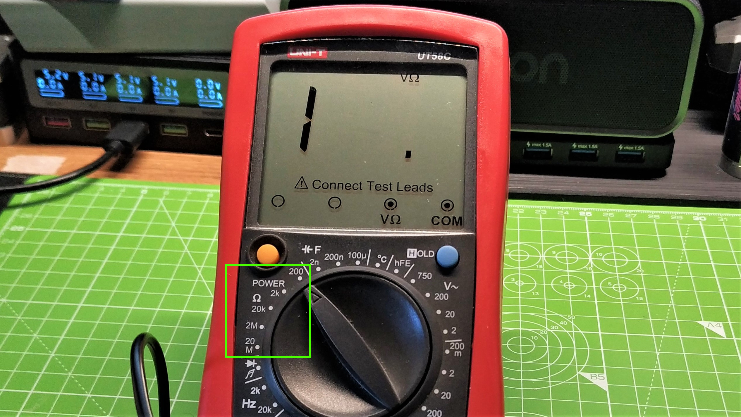
Multimeters are a vital device for makers. Amongst different options multimeters can measure voltages, present, and verify for continuity in a circuit. There are two frequent multimeters, auto-ranging and guide. Auto-ranging attempt to detect studying and put it into a spread. For guide we have now to set the vary.
For Auto-Ranging Multimeters
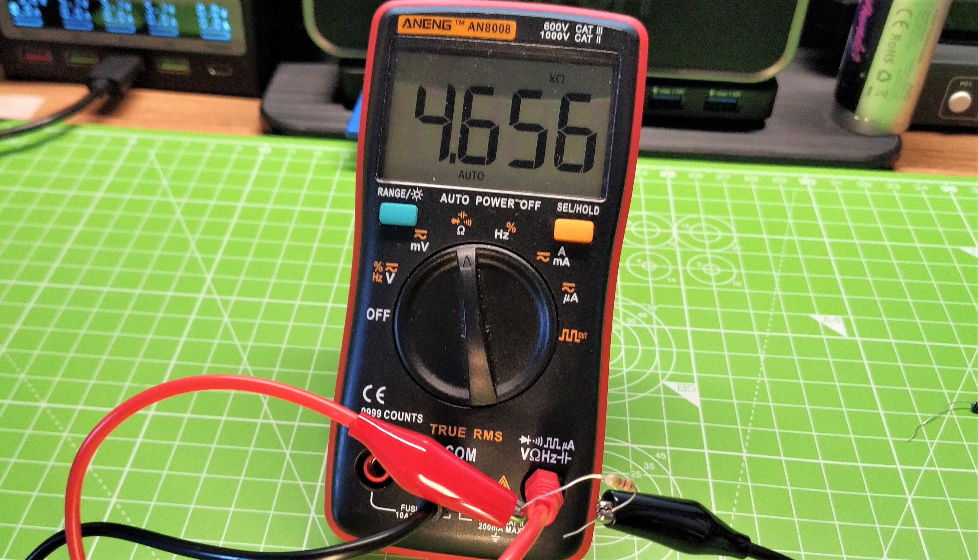
1. Flip the dial to the Ω (Ohm) image and press the facility button. Some multimeters will activate when the dial is turned, whereas others have an influence button.
2. Wrap one leg of the resistor round one probe. Resistors would not have a polarity so we are able to join both leg to the probe.
3. Wrap the opposite leg across the remaining probe.
4. Learn the worth from the display screen. Give it a couple of moments to settle earlier than taking a studying.
For Handbook Multimeters
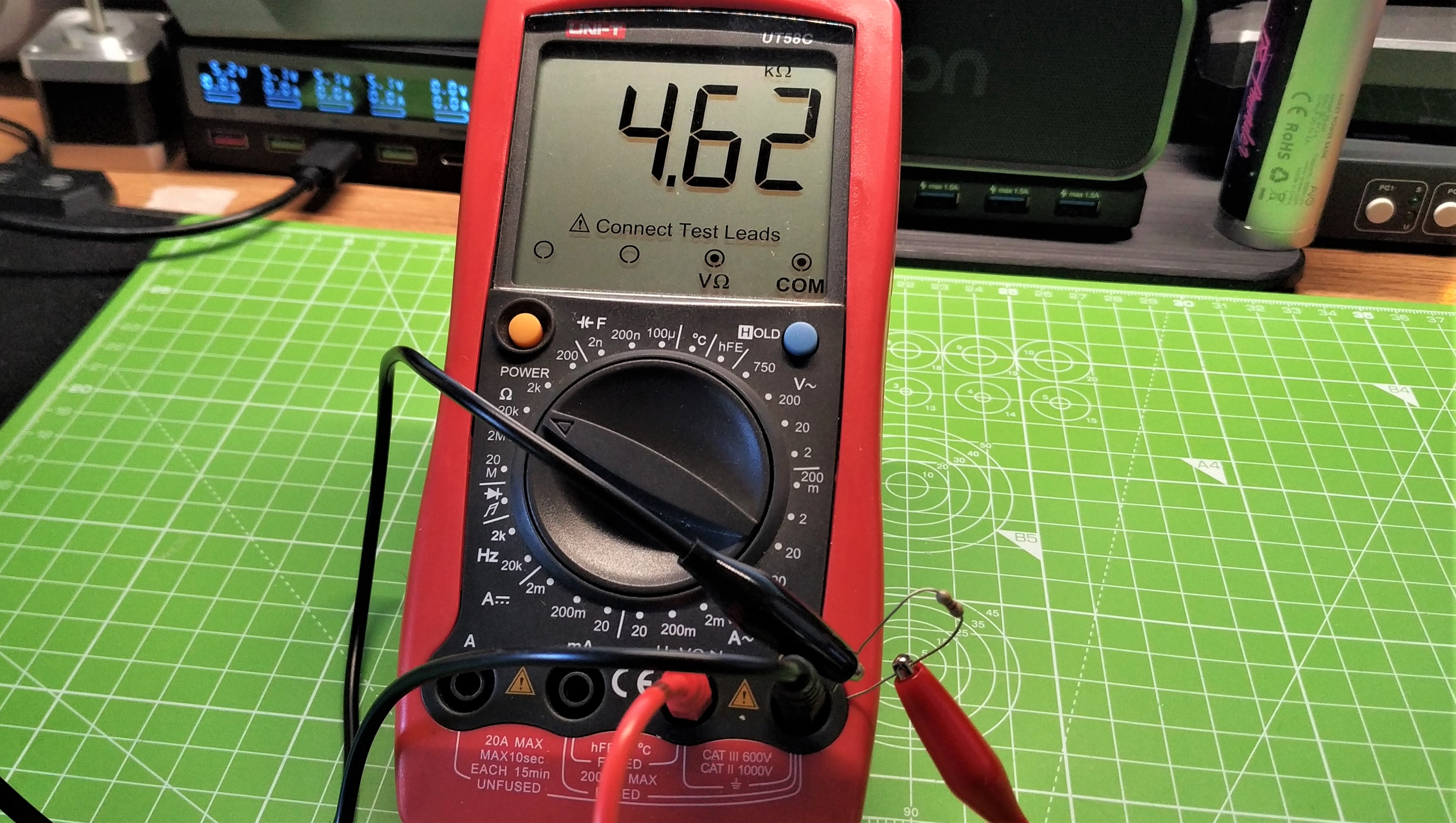
1. Flip the dial to the Ω (Ohm) image and choose the bottom vary. Press the facility button.
2. Wrap one leg of the resistor round one probe. Resistors would not have a polarity so we are able to join both leg to the probe.
3. Wrap the opposite leg across the remaining probe.
4. Learn the worth from the display screen. Give it a couple of moments to settle earlier than taking a studying.
5. If the studying states OL or garbled, go up one vary till you see a steady worth. That is the multimeter making an attempt to inform us that our studying is out of vary, usually increased than the guide setting we have now used.
