 This venture goals to develop a wearable security and alarming gadget that may be operated simply, particularly by kids and senior residents when in misery. It could come helpful because the world is continually witnessing improve within the variety of felony actions. Senior residents residing alone are susceptible to panic conditions attributable to security causes or, typically, a medical situation. This gadget can ship an SOS name and concurrently increase an alarm, if wanted.
The gadget most frequently used for such a objective is the SOS button. It’s a discreet gadget that lets the person ship an SOS alert to rapidly talk for assist from a trusted particular person through the use of GSM, GPS, or GPRS. It’s used particularly for anti-aggression alarms in jewelery shops, banks, or small companies, and for private security.
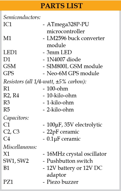 On this venture, we goal to construct a customized, cost-efficient model of the SOS button, which is stealthy and makes use of the perfect in school GSM-GPS modules together with a high-decibel buzzer. Its {hardware} interfacing on breadboard is proven in Fig. 1.
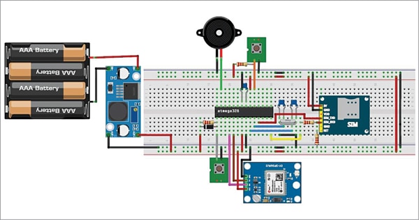
The parts used within the venture and their operate is described beneath.
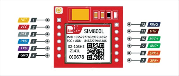
SIM800L is a miniature mobile module that enables GPRS transmission (sending and receiving), SMS, and voice calls. It’s a low-cost gadget with small footprint and quad band frequency. The module is an ideal answer for any venture that requires long-range connectivity. Pin particulars of SIM800L are proven in Fig. 2.
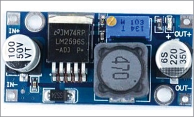
Buck converter (or step-down converter) is a DC to DC energy converter, which steps down voltage (whereas stepping up present) from its enter (provide) to its output (load). A DC-DC step-down converter mainly converts the next enter voltage to a decrease output voltage by ‘chopping’ it up by quickly switching the output energy. The buck converter module is proven in Fig. 3.
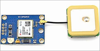
Neo-6M GPS module is a well-performing full GPS receiver with a built-in 25x25x4mm ceramic antenna, which supplies a powerful satellite tv for pc search functionality. With the ability and sign indicators the standing of the module will be monitored. The GPS module is proven in Fig. 4.
ATmega328P is the microcontroller utilized in an Arduino board. After importing the code into this microcontroller utilizing an Arduino board, it may be plugged out and used within the breadboard prototype.
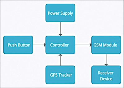
As proven within the block diagram (Fig. 5), there are additionally another parts like push buttons (SW1 and SW2), GPS module, GSM module, and energy provide. The circuit diagram of the venture is proven in Fig. 6. The microcontroller is, after all, the center of the venture.
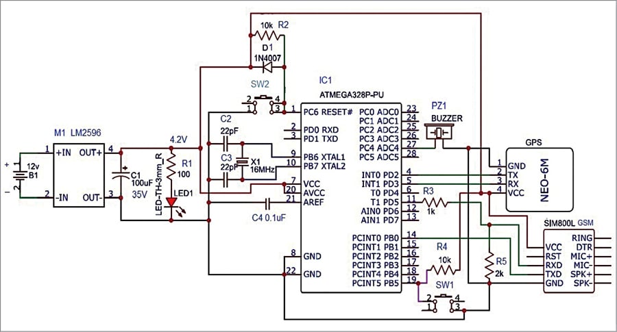
Each time the push button SW1 is pressed by the caller, the microcontroller provides the details about the caller, like his/her location and emergency SMS, to the registered quantity in GSM module. In consequence, the receiver cell receives caller’s SOS message.
As proven within the circuit diagram, push button SW2 is used to reset the circuit (at any time when there’s something flawed in this system). LED1 is used to point the presence of energy within the circuit. The circuit will be powered by a 4.2V provide from the converter LM2596 module.
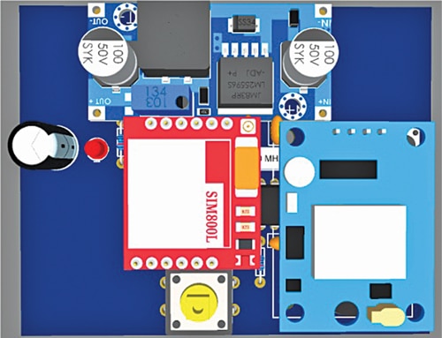
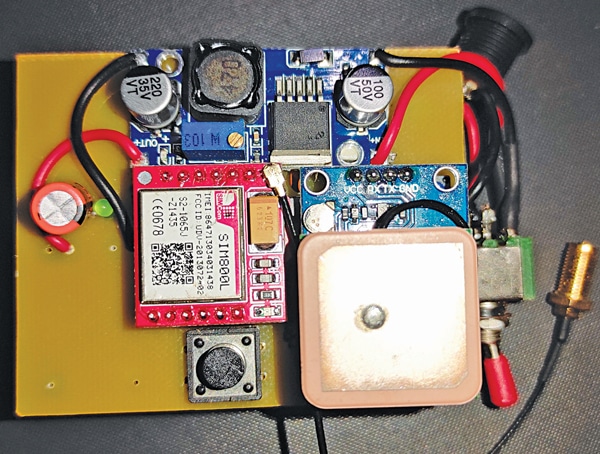
A 3D view of the prototype generated by the software program is proven in Fig. 7 and the writer’s prototype is proven in Fig. 8.
Software program
Arduino IDE 1.8.15 is used to put in writing, compile, and add the code (smart_SOS_final.ino) into the Arduino board. The code requires TinyGPS++.h header file. The header file will be downloaded from Hyperlink
Earlier than importing the code, enter a legitimate 10-digit cellphone quantity within the code
String quantity = “xxxxxxxxxx”;
the place ‘xxxxxxxxxx’ is the cellphone quantity to obtain the SOS message within the receiver’s cell phone.
Development and testing
EasyEDA is a free internet based mostly EDA (electronics design automation) software, which supplies facility to design schematic diagrams in addition to PCB layouts. After finishing schematic diagram on EasyEDA platform, choose DesignConvert schematic to PCB. Alter all of the parts of the circuit in greatest minimal house. Then choose RouteAuto route.
EasyEDA can generate 2D and 3D visualisations of the PCB. To get them, choose 2D View and 3D View, respectively. The 3D view is proven in Fig. 7.
Assemble the circuit on a breadboard or PCB. Insert the SIM card within the slot of GSM module. When SW1 is pressed, GSM calls the cell quantity already entered in this system code and the buzzer sounds. The buzzer sound is to alert close by individuals.
As soon as the decision is established, GPS will get latitude, longitude, and altitude coordinates and thus the precise location of the caller. The hyperlink of this location is distributed to the receiver’s cell phone together with the recorded SMS message. On opening the acquired hyperlink, the receiver will get to know the precise location of the caller on Google map.
Obtain Supply Code
Kamlesh Vasoya is an electronics hobbyist

