On this article, I can be having a look at what Shader Graph is; utilizing Shader Graph; the options of Shader Graph; methods to create a easy shader with Shader Graph; some helpful nodes with examples; and a few issues to look out for when taking a look at shaders created with older variations of Shader Graph. With this data, you have to be able to create some primary Shader Graph node results!
I’ll depart you with some extra assets that you may take a look at — these might help you create and customise your individual desired visible results that couldn’t be coated within the scope of this text.
Right here’s what you’ll study:
Shaders and why they’re necessary
Earlier than I get into Shader Graph, we have to know what shaders are and the way they have an effect on us.
Shaders are mini packages that run on the GPU which are used for texture mapping, lighting, or coloring objects. All the pieces that will get displayed on display (a pc program or recreation, to incorporate gaming consoles) goes by means of some kind of shader earlier than it’s displayed.
For many packages, that is in-built robotically behind the scenes. In 3D modeling, software program is normally added to the mannequin earlier than it’s lastly rendered. Movie studios use them to render results to the film, and video games use them to show every thing.
In the event you use Unity, you’re utilizing them with out even realizing it: every thing displayed has some kind of materials that makes use of a shader.
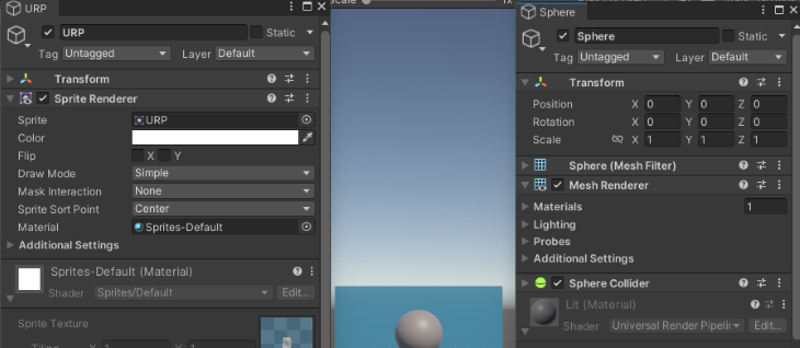
This picture illustrates among the several types of shaders accessible by default in Unity.
Now chances are you’ll be asking your self, If Unity already offers shaders that can be utilized, why can we care about shaders? The easy reply is that the default ones supplied are bland and don’t add something particular to be used, like water, holographic, ghost, glow, or dissolve results, simply to call a number of.
We are able to get a few of these results by altering the setting, just like the Floor Kind (Opaque or Clear), specifying Metallic or Specular, Smoothness, or including an Emission. The issue with that is they’re all static. What we would like are some dynamic results or customized settings that we will use so as to add some polish to the feel and appear of our recreation or utility.
Completely different results that we will receive with shaders
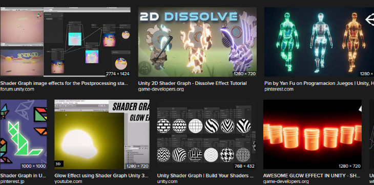
Let’s check out among the completely different shader results. These are only a small fraction of what’s attainable. Pictures are from an Web picture seek for “Shader Graph Unity results”:
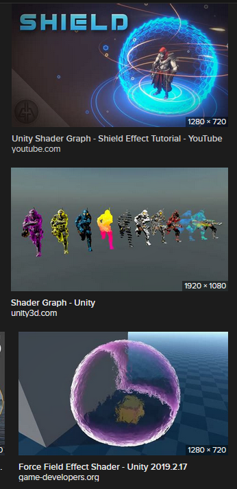
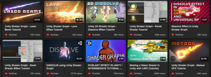
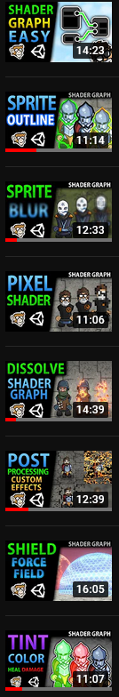
From a preferred YouTube programming channel:
Extra nice articles from LogRocket:
From the Unity weblog:
What’s Shader Graph?
Now that we all know what shaders are and see among the completely different attainable results that we will make from shaders, let’s check out how we will create these shaders.
Shaders was once created by means of code; through the years, completely different software program corporations have been including instruments that enable the creation of shaders by means of visible node-based techniques. Unity is not any completely different; they’ve given us Shader Graph.
Check with Unity’s Shader Graph options for the highlights: “Shader Graph lets you construct shaders visually. As an alternative of writing code, you create and join nodes in a graph framework. Shader Graph offers prompt suggestions that displays your adjustments, and it’s easy sufficient for customers who’re new to shader creation.”
Shader Graph was designed for artists, however programmers that aren’t shader programmers may also use it for straightforward shader creation. Hey, not all of us work with AAA studios which have the price range for a devoted crew of shader programmers/artists. Additionally, shaders can require plenty of data of advanced math and algorithms to hand-code.
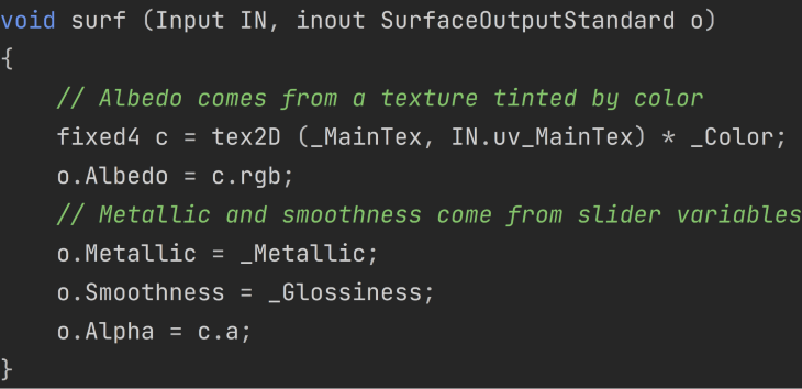
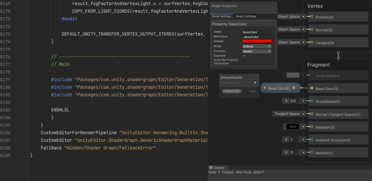
For instance, a snapshot of a brand new shader created in Unity does primary lighting of a mannequin with a texture for the colour. That is strains 1571 to 1580 of the 1685 strains of code:
What do I would like to make use of Shader Graph?
Unity notes these necessities to make use of Shader Graph:
Use Shader Graph with both of the Scriptable Render Pipelines (SRPs) accessible in Unity model 2018.1 and later:
As of Unity model 2021.2, it’s also possible to use Shader Graph with the Constructed-In Render Pipeline.
Because of this so long as we’re utilizing one of many SRPs that we will use Shader Graph out of the field.
Though we will set up it with the Bundle Supervisor and use it with the Constructed-In Render Pipeline, Unity goes on to state, “It’s really helpful to make use of Shader Graph with the Scriptable Render Pipelines.”
Step one is to create a brand new challenge in Unity Hub utilizing the URP or HDRP template (or set up one of many SRPs into an current challenge).
Create a challenge utilizing the URP or HDRP template.
As soon as the scene masses, I add a capsule to my scene that I can use to show my results with (be at liberty to make use of any 3D object that you really want, to incorporate your individual mannequin). I additionally create a cloth that I can apply my customized shader to and add it to my capsule.
Utilizing Shader Graph
Now that we’ve a really primary take a look at scene, let’s create a brand new Shader Graph. Proper click on > Create > Shader Graph > SRP you need to use > kind of shader.
In my case, I’m going to make use of URP > Lit Shader Graph.
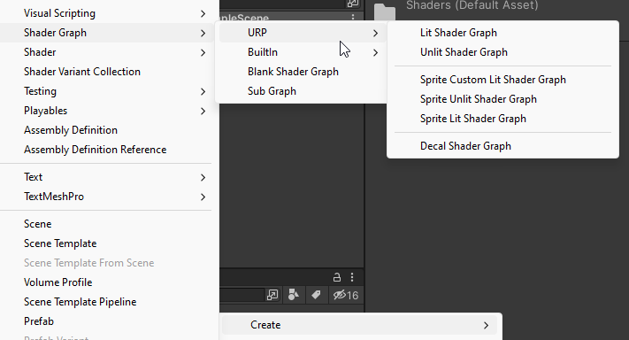
The Shader Graph menu will at all times include Clean Shader Graph (a very clean shader graph, no goal is chosen, and no blocks are added to the Grasp Stack) and Sub Graph (a clean Sub Graph asset, a reusable graph that can be utilized in different graphs) choices.
There needs to be a submenu for every put in render pipeline that accommodates template stacks. In my case, I’ve URP and inbuilt submenus. The template creates a brand new Shader Graph that has the Grasp Stack with default Blocks and a Goal chosen. You’ll be able to at all times change the settings in Shader Graph window later.
Now that we’ve a Shader Graph created, let’s set the fabric that we’re utilizing for this shader.
There are two methods to do that:
- Within the Inspector Window for the fabric (all Shader Graphs are within the Shader Graph submenu)
- Drag and drop the shader onto the fabric
Primary shader graph definitions and phrases
Now is an efficient time to pause and go over some helpful phrases, a few of which I’ve already used; i.e., Grasp Stack, Blocks, Goal.
- Areas — what the nodes count on their enter or outputs to be
- Object house — the place the objects’ vertices are relative to the middle/pivot level of the item
- World house — the place of the objects’ vertices are relative to a degree on this planet. This place is relative to the digicam’s place (camera-relative rendering) excluding the digicam’s rotation. In HDRP, there may be an added place known as absolute world house, which is a degree on this planet. In URP, world house and absolute world house are the identical
- Tangent house — relative to the vertex and its regular
- View/eye house — relative to the digicam’s ahead course, takes into consideration the rotation of the digicam
- Clip house — relative to the display, as soon as the view house is projected
Let’s additionally cowl some extra sophisticated phrases in depth.
Graph Goal (goal)
That is the render pipeline that the Shader Graph is for; you need to have the render pipeline put in in your challenge for it to be accessible within the checklist. Not all blocks are suitable with all targets.
You’ll be able to have a number of targets: this permits for straightforward creation of Shader Graphs that can be utilized in all render pipelines with out having to do duplicate work. This may be modified within the Graph Settings.
Properties and key phrases
Properties
These are variables that we will use to switch the shader’s values after it has complied.
For more information on properties, see the Unity docs.
All properties have the next settings. Different settings can be found relying on the info kind:
- Title — the identify that will get displayed for the property; i.e., within the Shader Grap
- Reference — the identify used internally by the shader. This should start with an
_. It’s robotically set to the Show Title; areas are transformed to_. You’ll be able to change it. This identify is used to entry the property by means of C# script with theMaterials.SetandMaterials.Getstrategies - Precision — for particulars, see Precision Modes | Shader Graph | 12.1.7
- Uncovered — if
true, the property can be uncovered within the Materials Inspector - Override Property Declaration — if enabled, the Override Property Declaration permits a Shader Declaration Enumeration
- Default — the worth to make use of as default for the property. This worth will depend on the info kind of the property
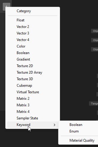
Key phrases
Key phrases are used to create completely different variants on your Shader Graph (the shader behaves otherwise relying on the worth of the key phrase).
Key phrases is a sophisticated characteristic and is past the scope of this text. As of scripting this, Materials High quality is the one kind that has settings not capable of change.
If you wish to hunt down extra about key phrases by yourself time, the Unity docs are a great place to start out.
Block node
Block nodes are a part of the Grasp Stack and are what the outputs of the shader nodes are related to. Completely different shader phases (Vertex or Fragment) have completely different Block nodes.
Vertex Stage
The place, regular and tangent, of the vertices.
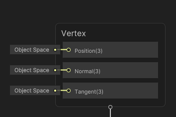
- Place — the place of the vertex after being moved by the shader
- Regular — the course the vertex factors
- Tangent — usually lies perpendicular to the vertex regular; it is suggested to alter this should you change the vertex regular
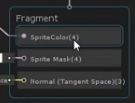
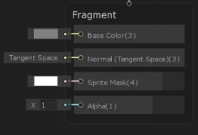
Fragment Stage
The Fragment Stage operates on the pixels after the Vertex Stage. That is the colour and lighting.
Which Blocks which are accessible will depend on the Goal Add Materials settings.
- Base Colour (albedo) — the colour of the item with out lighting affecting it. This can be a Vector3 shade, which means it is just the pink, blue, and inexperienced values
- Regular — that is used for Unity’s inbuilt lighting calculations
- Emission — the sunshine that the item emits
- Metallic — takes a float 0–1 how metallic an object is, solely when utilizing a metallic workflow
- Specular — takes a shade to have an effect on specular highlights, solely when utilizing the specular workflow
- Smoothness — 0–1 how clean an object is. Tough > Polished mirror
- Ambient Occlusion — 0–1 how a lot of the pixel is blocked by different gentle. Not Blocked > Absolutely Blocked (lighting is artificially decreased)
- Alpha — 0–1 how clear a pixel is. In sprites, that is usually the alpha of the colour from the feel of the sprite
- Alpha Clip Threshold — pixels under this threshold get culled
- Sprite Masks — not outlined in documentation. Grayed out in all supplies besides Sprite Gentle varieties
Node classes
Shader Graph has over 200 completely different nodes that can be utilized to create a shader; discuss with Unity’s Node Library for a element on all the nodes.
The nodes are organized by classes within the Create Node menu:
- Inventive nodes: Colours, shade channels, and texture operation
- Channel: The order and worth of every part of a vector
- Enter: Primary primitive varieties, sampling textures, and getting details about the mesh
- Math: Math operations
- Procedural: Procedural operations like noise
- Utility: Utility nodes, like Preview, Customized Shader Operate, and Logic
- UV: Remodel the UVs used to pattern textures
- Block: The nodes of the Grasp Stack; represents part of the floor used for the ultimate shader output. The Unity docs have extra data
To entry the Create Node menu, you’ll be able to right-click within the Shader Graph view and choose Create Node or press the spacebar. Nodes will be discovered by trying by means of the submenus or typing them within the search bar.
Nodes have enter ports and output ports. The completely different ports settle for completely different knowledge varieties relying on the node. Not all nodes have an enter port. As an example, the Block nodes don’t have any output port.
Unity tried to make Shader Graph extraordinarily person pleasant — this additionally helps with the debugging of your impact. They tried to make it so you’ll be able to see the outcomes of an impact alongside the best way as a lot as attainable. You don’t have to attend for the ultimate output to be related to see how issues change.
The Shader Graph window’s seven parts
The Shader Graph has seven most important parts to it. Let’s go over them so you’ll be able to change into accustomed to these home windows.
The principle window
That is the Shader Graph window itself. It accommodates (listed so as by view priority) the Toolbar, Blackboard, Graph Inspector, Essential Preview, Grasp Stack, and Nodes.
You’ll be able to zoom out and in with the scroll wheel, pan with the center mouse button, and drag-select with and transfer gadgets round with the left mouse button. To open this window, all we’ve to do is double-click on a Shader Graph Asset within the Mission view.
Blackboard
That is the place we will add the properties and key phrases. The Blackboard will be moved anyplace inside the principle view and is ready in a fashion that we will by no means lose it. It may be turned on and off.
Essential preview
This can be a preview of what the ultimate output of the shader will seem like. The principle preview will be moved anyplace throughout the Essential View and is ready in a fashion that we will by no means lose it. It may be turned on and off. You’ll be able to choose one of many inbuilt meshes to make use of or use a customized mesh (any mesh object that’s within the challenge).
Nodes
The nodes of the graph. This window will be moved anyplace inside the principle view, zoomed out and in, added and deleted.
Grasp Stack
The distinction between this node and all of the others is that we can’t add or delete it. It can at all times be displayed above all different nodes.
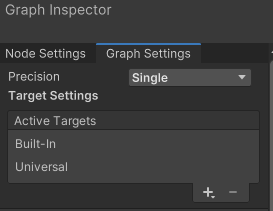
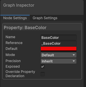
Graph Inspector
The Graph Inspector accommodates the Graph Settings and Node Settings tab. The Node Settings tab adjustments relying on which node/block/parameter/key phrase we’ve chosen.
This window will be moved anyplace inside the principle view and is ready in a fashion that we will by no means lose it. It may be turned on and off.
Toolbar
Everlasting on the prime of the window, the toolbar accommodates the File buttons on the left and the Colour Mode choice.
Helpful inbuilt Shader Graph options
The Shader Graph is packed stuffed with helpful options. These are a handful you’ll be utilizing incessantly; let’s see how one can make the most of them.
Accessing documentation
One useful merchandise is the flexibility to entry the documentation straight from a node. With the node chosen, press F1 on the keyboard.
Please word that although among the others within the window have the identical possibility, it doesn’t join all the time. In the event you run into that situation, delete what’s within the tackle bar after /handbook/, and within the Filter Content material, search for one of many key phrases.
Good connections
Connections between nodes should not allowed to be made between incompatible varieties. Once you attempt, as a substitute of constructing the connection, it would carry up the Create Node window that shows all the nodes that has an enter of the sort that you’re utilizing as an output and an output of the sort you are attempting to make use of for the enter.
For instance, I’ve a Texture Asset that I need to use for the Base Colour Block. The Texture2D Asset has an output Texture2D, however the Base Colour takes an enter of Vector3. When I attempt to join the output of the Texture2D Asset to the enter of the Base Colour Block, I get a Create Node menu that has all the nodes which have an enter of Texture2D and an output that’s suitable with a Vector3.
After I select Enter > Texture > Pattern Texture2D, I get a brand new Pattern Texture2D node that has a connection to the Texture2D asset node. Now all I have to do is decide which output of the Pattern Texture2D I need to use (I’ll use the RPGA, which is a Vector4).
Grouping
You’ll be able to group nodes collectively by clicking a dragging to pick out a gaggle.
Sticky Notes
Notes that can be utilized so as to add particulars, a to-do checklist, feedback, and many others.
Sub Graphs
Take a gaggle of nodes that carry out a particular perform and switch them right into a Sub Graph. These Sub Graphs will be reused in different graphs like another node. End up repeating the identical steps time and again in a number of shaders? Flip it right into a Sub Graph.
Discover the way it left the properties in the principle graph. Double-clicking on the Sub Graph opens it in a brand new Sub Graph window. The properties bought duplicated, however the defaults modified again to Unity defaults.
A number of Shader Graphs
You’ll be able to have a number of Shaper Graphs open at one time. Every Shader Graph or Sub Graph will open in its personal Shader Graph window. These home windows will be moved round identical to another window in Unity. You’ll be able to even copy nodes from one Shader Graph to a different.
Viewing the code for a node
Along with the node library documentation for a node, you’ll be able to generate the code for every node and choose Present Generated Code. This can open the code for that node in your code editor.
You may as well view the code for your entire shader by choosing it within the Mission view and choosing one of many view/present code buttons.
Creating your first shader
Now we’ve every thing wanted to create a easy shader. Let’s make a Lit shader that can be utilized in each the Constructed-In and URP that has a shade that may be set within the Inspector. If you wish to, embody HDRP simply guarantee that you’ve got HDRP added in your challenge.
Mission setup
To begin, create a Shader Graph asset and open it within the Shader Graph window. I’ve already created a Lit Shader Graph, so I simply double-click on it to open it. If in case you have not created one but, right-click > Create > Shader Graph > SRP you need to use > kind of shader.
In my case, I’m going to make use of URP > Lit Shader Graph.
Within the Graph Settings, guarantee that the Shader Graph has all of the targets listed. In my case, I exploit Constructed-in and Common (be at liberty to make use of only one, e.g., Common). Then be certain that every of them are set to Lit.
Subsequent, create a brand new node. I need to have the ability to change the colour, so I would like a shade node.
Join the node and set the output
Now the Colour node must be related to the Grasp Stack. To do that, I clicked on the Output of the Colour node and drag it to the Enter of the Base Colour. Discover that the connection up to date the Essential Preview.
Subsequent, I modified the output shade of the Colour node to a blue. Discover that this was up to date within the Essential Preview, too.
Observe that I may have executed the creation of the node and related it to the Base Colour Block in a single step. To do that, click on on the output of the Base Colour Block and drag to an empty house within the Shader Graph most important window.
Save the graph
For this for use in my scene, I’ve to ensure to avoid wasting the graph.
In fact, if it doesn’t seem on my object within the scene, then step one is to guarantee that the Render Part of the GameObject is utilizing a Materials that’s utilizing the shader.
Convert the colour to a property
The final requirement Is to make this shade settable within the Inspector. For this, I would like a property.
I can create a property within the Blackboard and add a brand new Colour Property.
Then both drag and drop it or use the Create Node menu and choose it within the Properties submenu.
I may also simplify this step and convert the Colour node that’s already within the graph to a property.
Crucial factor to notice is the Node Settings of the property. To ensure that it to be uncovered within the Inspector, we want to ensure the Uncovered setting is ready. The opposite setting that we have to be aware of is the Reference setting; that is the identify to make use of in C# scripts.
Don’t overlook to avoid wasting the asset.
The shader is full
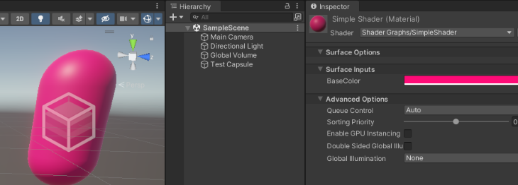
Now we will change the colour within the Materials’s Inspector.
This can be a quite simple shader, so let’s check out a side-by-side comparability of the code.
Utilizing Shader Graph is unquestionably simpler and faster. Technically, I bought two shaders as a result of it really works on two completely different render pipelines.
How one can use among the common nodes (with examples)
On this part, I’ll attempt to present among the widespread issues that shaders are used for and the nodes which are used to make them. I’ll present completely different nodes in every instance, however I won’t be able to undergo all 200+ nodes which are accessible.
If you wish to know what a unique node does that I don’t present right here, I recommend checking the documentation, including it to your Shader Graph, and seeing the way it works. Bear in mind: most nodes have their very own preview, so that you don’t have to attach it to something to see its results.
Most of those nodes are reusable and will be related collectively, so I’ll convert them to Sub Graphs, and the impact will be added to another Shader Graph. Each instance will use the Property node (in all probability multiple). The Property node works the identical as its base kind node with the distinction being that the Property node will be simply accessed from C# scripts and the Materials’s Inspector.
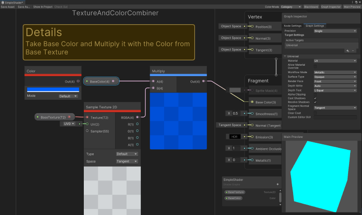
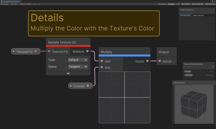
Texture and shade results
One of the basic items that you’ll want to obtain is to have a texture that’s related together with your mannequin and have it rendered as a shade. Sometimes, the bottom texture is mixed with a shade after which utilized to the ultimate output. Each the feel and shade are normally settable from throughout the Inspector.
New nodes you’ll study for the colour and texture results
Colour Node
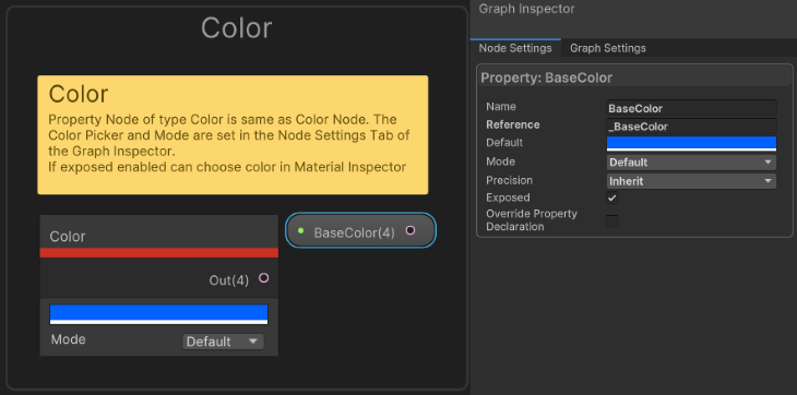
Colour outputs a Vector4 representing an RPGA worth. The Mode is Default or HDR.
Texture 2D Asset Node
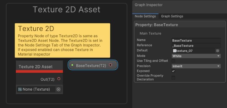
Lets you choose a Texture2D from the challenge’s belongings. Used together with Pattern Texture2D [LOD] node varieties. Permits a Texture2D to be loaded as soon as and sampled a number of occasions.
The Texture2D property offers two extra settings not accessible with the Texture2D Asset mode:
If the Texture will not be set, then it outputs a clean texture.
You’ll be able to select White, Black, Gray, Regular Map, Linear Gray, or Purple.
To make use of Tiling and Offset, set to false as a way to manipulate scale and offset individually, used from different texture properties like in Cut up Texture Remodel Node | Shader Graph | 12.1.7.
Pattern Texture2D Node
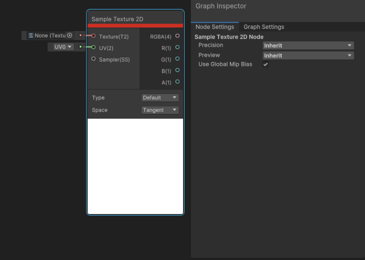
Pattern Texture2D takes a Texture2D and returns a Vector4 shade (RGBA). This may solely be used within the Fragment Shader stage. For the Vertex Shader stage, use Pattern Texture2D LOD node as a substitute.
The settings Node Settings > Use World Mip Bias allow the automated world mip bias (set throughout sure algorithms to enhance element reconstruction) imposed by the runtime.
Node Settings > Preview: Inherit, Preview 2D, and Preview 3D are the sort for the Preview space.
The feel kind is Kind: Default or Regular, and the house of the traditional will be Tangent or Object. (Kind should = Regular).
These are Pattern Texture2D’s inputs:
- Texture: Texture2D to Pattern
- UV: (UV) Vector2 representing UV Coordinates. U[0–3] or present your individual
- Sampler: (Default sampler state) The Sampler to make use of. For extra particulars, see Sampler State Node | Shader Graph | 12.1.7
And its outputs:
- RGBA: Vector4 shade
- R: Float pink (x) of RGBA
- B: Float blue (x) of RGBA
- G: Float inexperienced (x) of RGBA
- A: Float alpha (x) of RGBA
The Preview is a visible illustration of what’s output in (RBGA).
Pattern Texture2D LOD Node
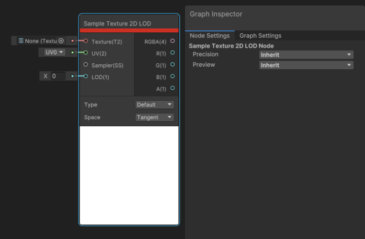
Pattern Texture2D LOD takes a Texture2D and returns a Vector4 shade (RGBA). That is solely helpful for the Vertex Shader stage. Some platforms (unsupported) could return opaque black as a substitute.
Some settings to recollect:
- Node Settings > Use World Mip Bias: Permits the automated world mip bias (set throughout sure algorithms to enhance element reconstruction) imposed by the runtime
- Node Settings > Preview: Inherit, Preview 2D, Preview 3D — the sort for the Preview space
- Kind: Default, Regular — the feel kind
- House: Tangent, Object — the house of the traditional (Kind should = Regular)
Pattern Texture 2D LOD’s inputs:
- Texture: Texture2D to pattern
- UV: (UV) Vector2 representing UV Coordinates. U[0–3] or present your individual
- Sampler: (Default sampler state) The sampler to make use of. For extra particulars, see Sampler State Node | Shader Graph | 12.1.7
- LOD: The Degree of Element to pattern
Pattern Texture2D LOD outputs:
- RGBA: Vector4 Colour
- R: Float pink (x) of RGBA
- B: Float blue (x) of RGBA
- G: Float inexperienced (x) of RGBA
- A: Float alpha (x) of RGBA
Multiply Node
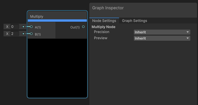
Because the identify suggests, the Multiply node multiplies enter A by enter B.
- Node Settings > Preview: Inherit, Preview 2D, Preview 3D — the sort for the Preview space
Multiply inputs:
- A: Vector or Matrix
- B: Vector or Matrix
Multiply outputs:
- Vector or Matrix (will depend on the kinds of Enter A and B)
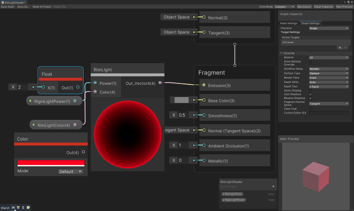
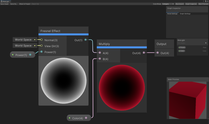
Rim gentle impact
For this, we’ll construct a rim gentle that has a Colour and Energy uncovered within the Inspector.
The brand new node you’ll study for the rim gentle impact
Fresnel Impact
This node approximates a Fresnel Impact by calculating the angle between the floor regular and the view course. That is typically used to realize rim lighting, widespread in lots of artwork kinds.
- Node Settings > Preview: Inherit, Preview 2D, Preview 3D — the sort for the Preview space
Inputs:
- Regular: Vector3 — the house to make use of for the traditional
- View Dir: Vector3 — the view course to make use of
- Energy: Exponent of the ability calculation
Outputs:
- Float, representing a Fresnel Impact
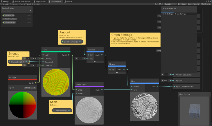
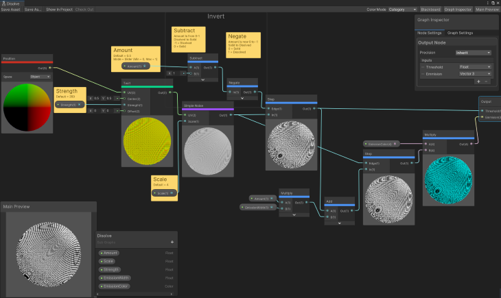
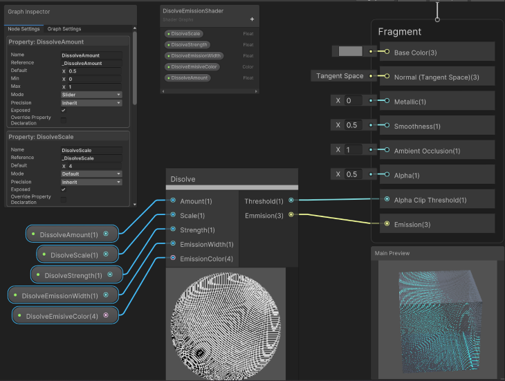
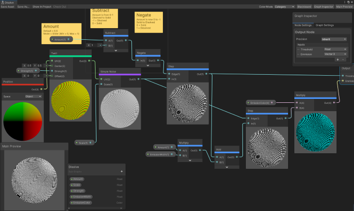
Dissolve impact
This can be a actually cool impact that’s used on a regular basis. Some examples are bringing a recreation object into/out of a scene, destroying issues which are on fireplace, or in a personality editor altering the character (you dissolve the previous character out and a brand new character in).
You’ll be able to enhance the DissolveScale whereas reducing the DissolveAmount and you may get an fascinating impact.
Be sure you allow Alpha Clipping within the Graph Settings and set the Alpha Block to 0.5.
In order for you the within of the mannequin to render, set Render Face to Each, else set to Entrance.
New nodes you’ll study with the dissolve impact
Easy Noise Node
Easy Noise generates a Worth Node based mostly on the UV Enter scaled by the Scale Enter. There are a few different noise nodes that can be utilized relying on the kind of noise you need (e.g., the Gradient Noise Node generates Perlin noise, and Voronoi Node generates Worley noise).
Inputs:
- UV: (UV) Vector2 UV worth
- Scale: Float quantity to scale the Enter UV by
Outputs:
- Float, representing the noise
Step Node
Step returns a 1 (true, white) or 0 (false, black) if the worth enter is above or equal to the worth of enter Edge.
- Node Settings > Preview: Inherit, Preview 2D, Preview 3D — the sort for the Preview space
Step Node inputs:
- Edge: Dynamic Vector representing the Step worth
- In: Dynamic Vector representing the Enter worth
Step Node outputs:
- Dynamic Vector (0 or 1) if Enter worth (In) is bigger than or equal to the step worth (Edge)
Place Node
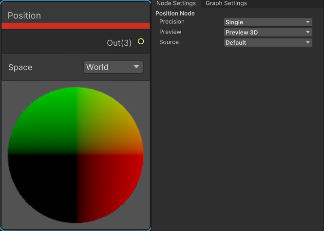
The Place Node offers entry to the place of the vertex of the mesh; the place is relative to the chosen house.
- Node Settings > Preview: Inherit, Preview 2D, Preview 3D — the sort for the Preview space
- House: That is the house of the coordinate. It may be Object, View, World, Tangent, or Absolute World
For instance, right here’s what occurs when the Place Node is related to the Easy Noise Node’s UV enter within the Dissolve Shader.
That is the end result if House = World:


And that is the end result if House = View:


Twirl Node
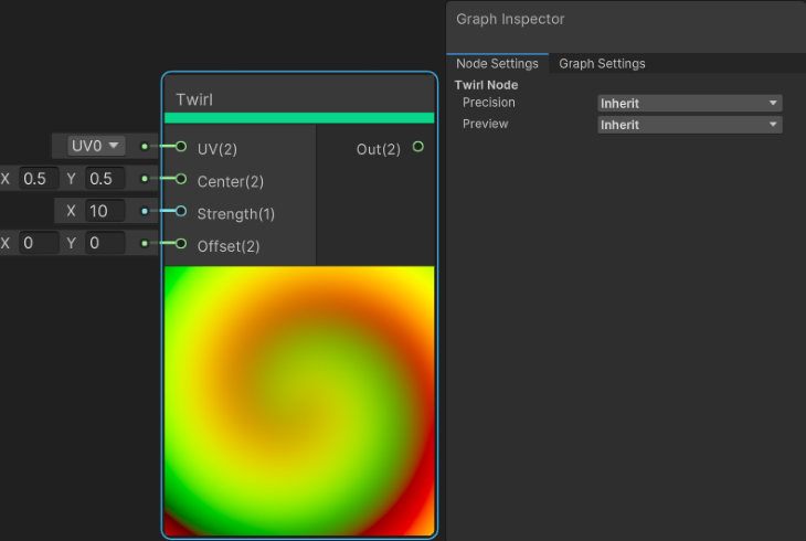
The Twirl Node applies a black gap–like warping impact to the worth of enter UV.
Node Settings > Preview: Inherit, Preview 2D, Preview 3D — the sort for the Preview space
Inputs:
- UV: (UV) Vector2, the Enter UV worth
- Heart: Vector2, reference level to the middle
- Power: Float, how sturdy the impact is
- Offset: The enter UV worth
Outputs:
- Vector2, the brand new UV worth
Preview: Visible Illustration of what’s outputted.
Checkerboard Node
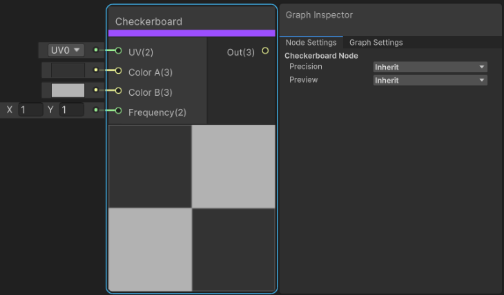
This generates a checkerboard with the colours supplied; the size is outlined by the Frequency. This node is used to use a checkerboard texture to a mesh, additionally helpful for a visible in Shader Graph on what the impact of adjusting the UV by some worth seems like.
- Node Settings > Preview: Inherit, Preview 2D, Preview 3D — the sort for the Preview space
Inputs:
- UV: (UV) Vector2, the UV worth
- Colour A: Vector3, shade of first checker
- Colour B: Vector3, shade of second checker
- Frequency: Scale per UV axis
Outputs:
- Out: Vector2, the UV worth
Subtract Node
This node subtracts Enter B from Enter A
- Node Settings > Preview: Inherit, Preview 2D, Preview 3D — the sort for the Preview space
Inputs:
- A: Dynamic Vector, first enter worth
- B: Dynamic Vector, second enter worth
Outputs:
- Out: Dynamic Vector, end result
Preview:
- Black end result <=0 to white end result >= 1
Negate Node
Negate flips the signal worth of In. Optimistic values at the moment are unfavorable and unfavorable values at the moment are constructive.
- Node Settings > Preview: Inherit, Preview 2D, Preview 3D — the sort for the Preview space
Inputs:
- In: Dynamic Vector, worth to flip
Outputs:
- Out: Dynamic Vector, results of flipping signal
Preview:
- Black end result <=0 to white end result >= 1
Dissolve with emission impact
With the addition of yet another node, we will have the dissolve impact emit gentle.
To assist hold issues neat and simple to learn, I made the dissolve impact a Sub Graph. I outputted the Step Node (that is what we had connected to the Alpha Threshold) and the Emission (we are going to want this for the Emission Block).
Dissolve with emission nodes
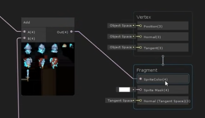
Add Node
Add the 2 inputs collectively.
- Node Settings > Preview: Inherit, Preview 2D, Preview 3D — the sort for the Preview space
Inputs:
- A: Dynamic Vector, first enter worth
- B: Dynamic Vector, second enter worth
Outputs:
- Out: Dynamic Vector, end result
Preview:
- Black end result <=0 to white end result >= 1
Sub Graph
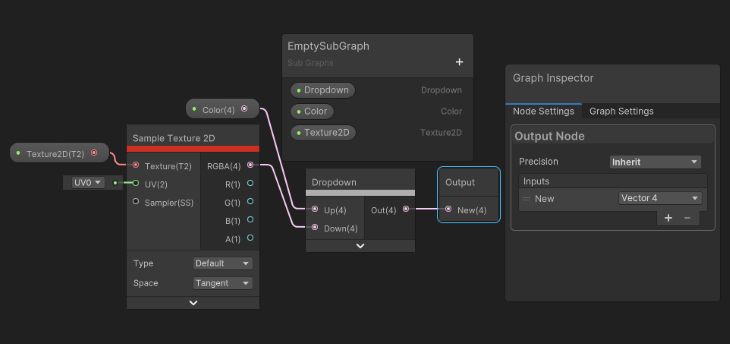
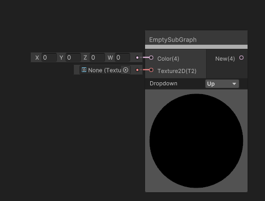
This lets you add any of your customized created Sub Graphs.
- Node Settings > Preview: Inherit, Preview 2D, Preview 3D — the sort for the Preview space
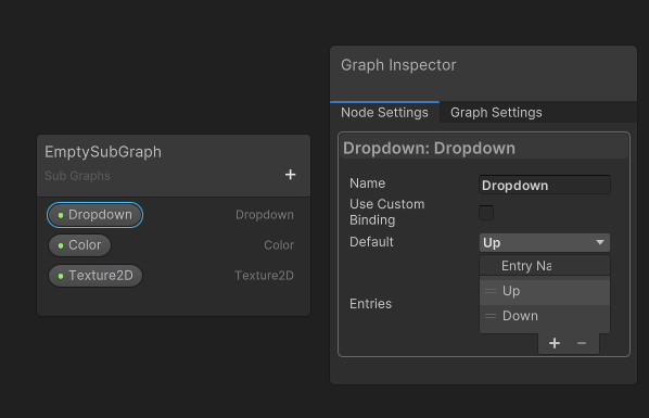
You’ll be able to embody any dropdown properties outlined on the Blackboard. For more information, see Subgraph Dropdown within the docs.
Inputs:
- The properties that you’ve got outlined within the Blackboard.
Outputs:
- What you outlined within the Sub Graph Output Node. Should have a minimum of one output
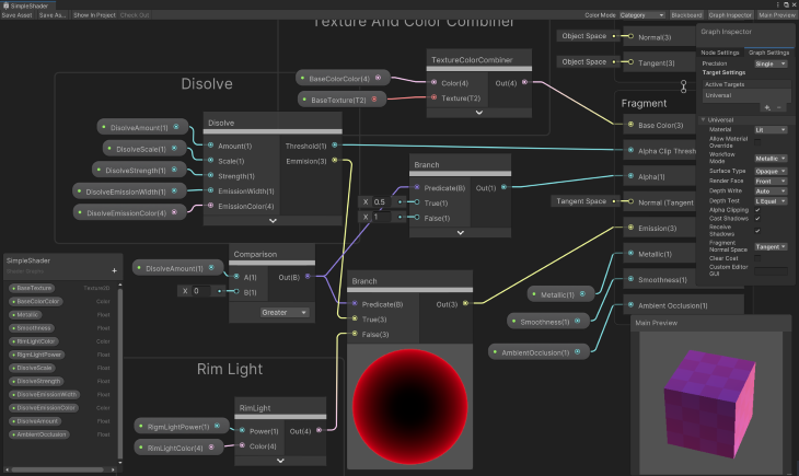
Mix them collectively
Now it’s time to mix all of those into one Shader Graph.
Listed here are every of the earlier results as a Sub Graph:
And the Shader Graph, utilizing all of them collectively:
Nodes for combining these all collectively
Comparability Node
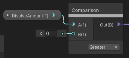
This node compares two values to a situation. It’s one of many many logic take a look at nodes accessible; others are ALL, And, Any, Is Entrance Face, Is Infinite, Is NaN Nand, Not, and Or.
- Node Settings > Preview: Inherit, Preview 2D, Preview 3D — the sort for the Preview space
- Dropdown: Equal, NotEqual, Much less, LessOrEqual, Grater, GreaterOrEqual — the situation to make use of for comparability
Inputs:
- A: Float to check to
- B: Float to check with
Outputs:
Out: Boolean results of comparability
The Preview is a visible illustration of what’s outputted.
Department Node
The Department Node returns a worth based mostly on a real/false situation. The opposite Branching Node is BranchOnInputConnection.
- Node Settings > Preview: Inherit, Preview 2D, Preview 3D — the sort for the Preview space
Inputs:
- Predicate: Boolean, determines which enter to make use of
- True: Dynamic Vector, worth to make use of if Predicate is true
- False: Dynamic Vector, worth to make use of if Predicate is fake
Outputs:
- Out: both the True or False Enter
The Preview is a visible illustration of what’s outputted.
Variations between new and previous Shader Graph variations
There are some issues to be aware of in variations of Shader Graph which are older than model 10.0.x, whether or not you’re upgrading from an older model or come throughout how somebody created a shader and need to replicate it.
The large distinction is using Grasp Stack as a substitute of Grasp Nodes. What Blocks can be found within the Grasp Stack will depend on your Graph Settings. Using a number of Grasp Nodes wants particular consideration. If you’re upgrading, see Unity’s improve information.
The opposite huge distinction between the 2: all the settings at the moment are discovered within the Graph Inspector. The Graph Settings tab accommodates all the graph-wide settings and the Node Settings tab accommodates all the property settings and per-node settings.
There are some minor adjustments within the Graph Settings, like Two Facet will not be a checkbox, and you utilize the Render Face enum (Entrance, Again, and Each).
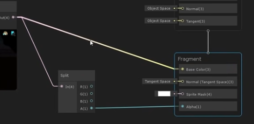
One final distinction is the enter for the Colour Block of a Fragment Stack. This tip truly comes from Code Monkey’s video.
The Fragment Stack will include a Colour Block that takes a Vector4 worth, which is RPGA. A newly created Shader Graph can have a Colour Block that takes a Vector3 worth, which is simply the RPG shade, and it has a separate block for the alpha.
To get the alpha, you simply add a Cut up Node and take the alpha output to the Alpha Block enter. He identified that particularly for sprites, usually when coping with shaders, in case you are utilizing the alpha of a shade, you’re particular about what the alpha worth represents. Whereas with sprites, the expectation is that the alpha of the colour controls the transparency.
Further assets
Unity has a number of extra assets should you’d wish to continue to learn:
