Espressif’s ESP8266 is a Wi-Fi SoC. It has all of the bells and whistles for Wi-Fi Community connectivity in addition to a really highly effective processor. You’ll be able to construct purposes utilizing ESP8266 SoC alone however when you’ve got a bunch MCU, then it may act as a slave as properly. There are ESP8266 modules accessible available in the market that you should use in your tasks. However earlier than beginning, you need to be aware of the pinout of the SoC in addition to the module. So, on this tutorial, we’ll check out the ESP8266 Pinout.
First, we’ll see the pinout of the ESP8266 SoC. As ESP8266 Wi-Fi Chip is out there in a number of modules, we may even see the pinout of a few of these modules.
A Temporary Be aware on ESP8266
The ESP8266 Wi-Fi Module modified the DIY and Hobbyist scene utterly. It paved the best way for small creators to construct IoT and ‘Sensible’ issues. You’ll be able to design a Sensible Bulb or Sensible Relay utilizing ESP8266.
Because it has a robust microprocessor, you should use it as a standalone system for the processor in addition to for Wi-Fi connectivity. However the advantage of ESP8266 is that you should use one other processor because the ‘major processing unit’ and use the ESP8266 simply as a Wi-Fi chip.
ESP3266 Pinout
We are going to begin understanding the pins of the ESP8266 with the principle SoC itself. ESP8266 SoC is out there in a 32-pin QFN Package deal (33 for those who think about the middle GND pad).
The next picture reveals the pin format of the ESP8266 SoC.
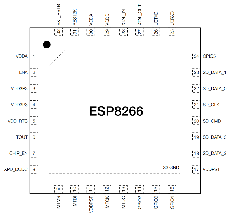
From the above ESP8266 Pinout, you possibly can see that it has only one pin (Pin 2 – LNA) for the RF Interface. This reveals the extent of integration ESP8266 has. Coming to the pins themselves, the next desk reveals the pin description of all of the ESP8266 pins.
| Pin Quantity | Title | Description |
| 1 | VDDA | Analog Energy Provide |
| 2 | LNA | RF Antenna Interface |
| 3 | VDD3P3 | Amplifier Energy Provide |
| 4 | VDD3P3 | Amplifier Energy Provide |
| 5 | VDD_RTC | NC |
| 6 | TOUT | ADC Pin |
| 7 | CHIP_EN | Chip Allow |
| 8 | XPD_DCDC | Deep Sleep Wakeup |
| 9 | MTMS | GPIO 14 / HSPI_CLK |
| 10 | MTDI | GPIO 12 / HSPI_MISO |
| 11 | VDDPST | Digital IO Energy Provide |
| 12 | MTCK | GPIO 13 / HSPI_MOSI / UART0_CTS |
| 13 | MTDO | GPIO 15 / HSPI_CS / UART0_RTS |
| 14 | GPIO 2 | GPIO 2 / UART TXs |
| 15 | GPIO 0 | GPIO 0 / SPI_CS2 |
| 16 | GPIO 4 | GPIO 4 |
| 17 | VDDPST | Digital IO Energy Provide |
| 18 | SDIO_DATA_2 | SD_D2 / SPIHD / HSPIHD / GPIO 9 |
| 19 | SDIO_DATA_3 | SD_D3 / SPIWP / HSPIWP / GPIO 10 |
| 20 | SDIO_CMD | SD_CMD / SPI_CS0 / GPIO 11 |
| 21 | SDIO_CLK | SD_CLK / SPI_CLK / GPIO 6 |
| 22 | SDIO_DATA_0 | SD_D0 / SPI_MISO / GPIO 7 |
| 23 | SDIO_DATA_1 | SD_D1 / SPI_MOSI / GPIO 8 |
| 24 | GPIO 5 | GPIO 5 |
| 25 | U0RXD | UART RX / GPIO 3 |
| 26 | U0TXD | UART TX / GPIO 1 / SPI_CS1 |
| 27 | XTAL_OUT | Crystal Oscillator Output |
| 28 | XTAL_IN | Crystal Oscillator Enter |
| 29 | VDDD | Analog Energy Provide |
| 30 | VDDA | Analog Energy Provide |
| 31 | RES12K | Serial Reference to 12 KΩ Resistor |
| 32 | EXT_RSTB | Exterior Reset Sign |
| 33 | GND | Floor Pad |
ESP-01 Pinout
The ESP-01 is without doubt one of the easiest ESP8266 modules accessible right now. Ai-Thinker developed this module. It has the principle SoC, crystal oscillator, flash reminiscence, and a PCB antenna.
There are additionally 8 fundamental pins for programming in addition to energy. The next picture reveals the pins format of ESP-01.
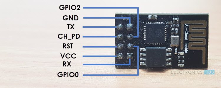
Out of the 33 pins of ESP8266 SoC, the ESP-01 Module
| Pin Title | Pin Perform |
| VCC | Energy Provide – 3.3V solely |
| GND | Floor |
| TX | UART TX |
| RX | UART RX |
| RST | Reset |
| CH_PD | Chip Allow |
| GPIO 0 | GPIO 0 |
| GPIO 2 | GPIO 2 |
NodeMCU Pinout
Whereas ESP-01 is the naked minimal ESP8266 Module, the NodeMCU is a well-liked compressive answer. It’s a correct ESP8266 Improvement board with all the required connectors and parts.
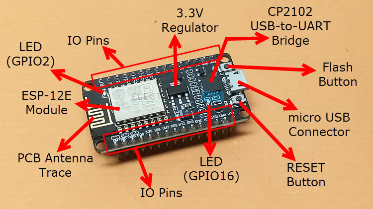
NodeMCU makes use of ESP-12E Module, once more by Ai-Thinker. This module, just like the ESP-01, has the SoC, Crystal Oscillator, and Wi-Fi Antenna. All of the important issues for ESP8266 SoC. The primary distinction between ESP-01 and ESP-12E is the variety of GPIO Pins.
Coming again to NodeMCU, it takes the ESP-12E as the bottom board and builds an entire system round it. The next picture reveals the Pinout of NodeMCU.
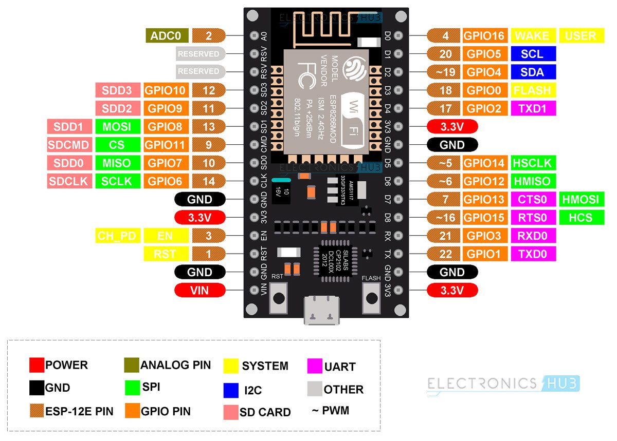
It has 30 pins. You’ll be able to see the pin description of all these 30 pins within the following desk.
| Pin | Description | Alternate Features | Default |
| ADC0 | Analog Enter | — | ADC0 |
| Reserved | — | — | |
| Reserved | — | — | |
| SDD3 | SDIO Information 3 | GPIO10 | SDD3 |
| SDD2 | SDIO Information 2 | GPIO9 | SDD2 |
| SDD1 | SDIO Information 1 | GPIO8 | SDD1 |
| SDDCMD | SDIO CMD | GPIO11 | SDDCMD |
| SDD0 | SDIO Information 0 | GPIO7 | SDD0 |
| SDCLK | SDIO CLK | GPIO6 | SDCLK |
| GND | Floor | — | — |
| 3.3V | 3.3V Output | — | — |
| EN | Chip Allow (Energetic HIGH) | — | — |
| RST | Reset (Energetic LOW) | — | — |
| GND | Floor | — | — |
| VIN | 5V Enter to three.3V Regulator | — | — |
| 3.3V | 3.3V Output | — | — |
| GND | Floor | — | — |
| TXD0 | UART0 TXD | GPIO1 | TXD0 |
| RXD0 | USRT0 RXD | GPIO3 | RXD0 |
| GPIO15 | GPIO15 | HSPI_CS / RTS0 | GPIO15 |
| GPIO13 | GPIO13 | HSPI_MOSI / CTS0 | GPIO13 |
| GPIO12 | GPIO12 | HSPI_MISO | GPIO12 |
| GPIO14 | GPIO14 | HSPI_SCK | GPIO14 |
| GND | Floor | — | — |
| 3.3V | 3.3V Output | — | — |
| GPIO2 | GPIO2 | UART1 TXD | GPIO2 |
| Flash | Flash | GPIO0 | Flash |
| GPIO4 | GPIO4 | Software program SDA (I2C) | GPIO4 |
| GPIO5 | GPIO5 | Software program SCL (I2C) | GPIO5 |
| GPIO16 | GPIO16 | Wake (deep sleep) | GPIO16 |
ESP-12E Pinout
You’ll be able to design your personal NodeMCU when you’ve got the ESP-12E Module. For that, you should be aware of the Pinout of ESP-12E. The next picture reveals the pinout of the ESP-12E Module.
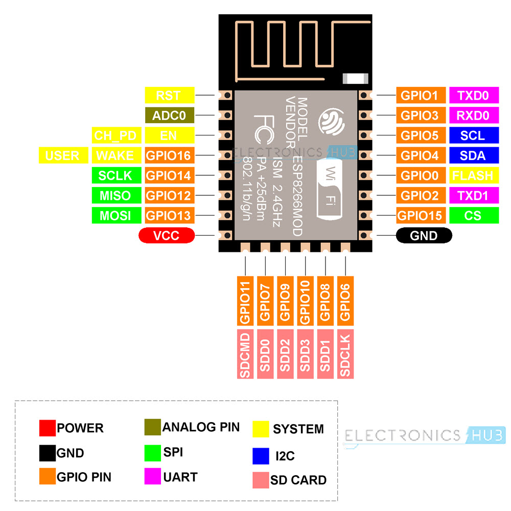
Right here is the pin description of all of the ESP-12E Pins.
| Pin | Perform |
| RST | Reset the Module |
| ADC0 | ADC Pin with 10-bit decision |
| EN | Chip Allow Pin (energetic HIGH) |
| GPIO16 | GPIO16 pin (wake pin from deep sleep mode) |
| GPIO14 | GPIO14 pin (HSPI_CLK) |
| GPIO12 | GPIO12 pin (HSPI_MISO) |
| GPIO13 | GPIO13 pin (HSPI_MOSI) |
| VCC | 3.3V Energy Provide (max 3.6V) |
| SDCMD | SDIO CMD (GPIO11) |
| SDD0 | SDIO Information 0 (GPIO7) |
| SDD2 | SDIO Information 2 (GPIO9) |
| SDD3 | SDIO Information 3 (GPIO10) |
| SDD1 | SDIO Information 1 (GPIO8) |
| SCCLK | SDIO CLK (GPIO6) |
| GND | Floor Pin |
| GPIO15 | GPIO15 pin (HSPI_CS) |
| GPIO2 | GPIO2 pin (TXD1) |
| Flash | Flash Pin (GPIO0) |
| GPIO4 | GPIO4 pin (SDA – software program I2C) |
| GPIO5 | GPIO5 pin (SCL – software program I2C) |
| RXD0 | UART0 RXD pin (GPIO3) |
| TXD0 | UART0 TXD (GPIO1) |
Conclusion
Despite the fact that ESP32 is a extra highly effective and succesful SoC, the ESP8266 remains to be one of many well-liked decisions for Wi-Fi Chips. A number of DIY, in addition to skilled merchandise, combine ESP8266 in a single type or the opposite. That’s both straight as an SoC or as a Module.
Regardless, if you wish to design tasks utilizing ESP8266, then you need to be aware of the pins and pin features. On this information, we noticed the ESP8266 Pinout. First, we noticed the pinout of the principle ESP8266 SoC.
Then we noticed the pinouts of some well-liked modules equivalent to ESP-01 and ESP-12E. We additionally seemed on the pinout of NodeMCU.
