 It’s an IoT primarily based mission by which you’ll be able to management 4 residence home equipment utilizing Apple HomeKit, Hey Siri app, and ESP8266 Wi-Fi module. The creator’s prototype is proven in Fig. 1.
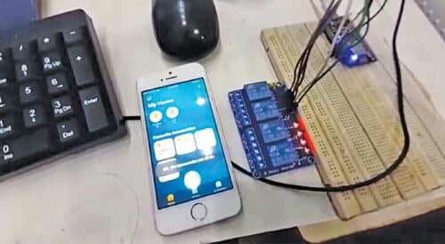
A couple of months in the past we have been considering of constructing a house automation system. After looking out on the web we discovered that such tasks have been primarily primarily based on Google Assistant and Alexa. From there we obtained the concept to make a house automation system that might be managed utilizing Apple’s assistant, the Hey Siri function.

We searched this matter however a lot of the articles written required Apple’s laptop computer and Homebridge app. We needed to make the mission with out utilizing these instruments. Then we got here throughout an incredible library that might make it attainable, although it had an instance to manage just one relay. Right here is the house automation mission by which you’ll be able to management 4 home equipment by 4 relays.

Following {hardware} is required to make the mission:
- 5V relay module
- NodeMCU board
- Jumper wires
- Bulb holder (for 230V AC)
- 60W/100W bulb
- iPhone SE or any iPhone that helps Apple HomeKit utility

Circuit
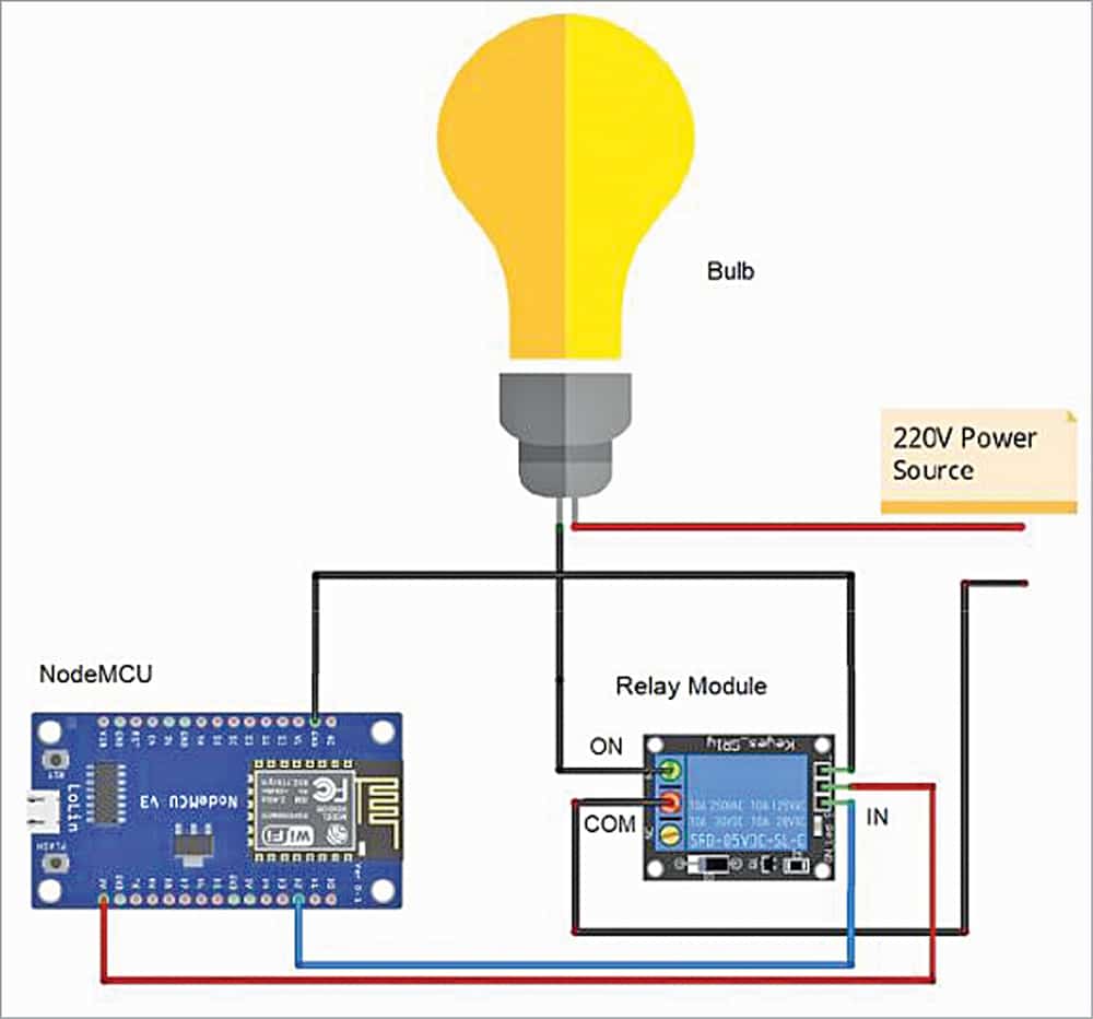
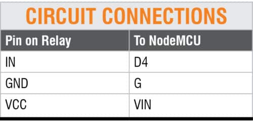
Circuit connections are quite simple. The Desk exhibits connections between relay module and NodeMCU. The entire connection diagram for controlling a bulb by a relay module is proven in Fig. 6. You possibly can join the circuit in an identical method to management the remaining three electrical home equipment.

There are two wires within the bulb holder, as proven in Fig. 6. Minimize one of many wires within the center and join one of many minimize ends to COM pin and the opposite to NO terminal of the relay module. Join pin D2 of NodeMCU to IN pin of the relay module.
 Software program
Obtain the Arduino-HomeKit library from the hyperlink.
After downloading, open Arduino IDE and comply with the steps given beneath.
- From the Arduino IDE, click on on Sketch after which Embody Library choice, as proven in Fig. 7. Subsequent click on on Add .Zip Library and choose HomeKit-ESP8266 library. The three recordsdata Example02_Switch, my_accessory.c, and wifi_info.h can be included within the Arduino IDE.
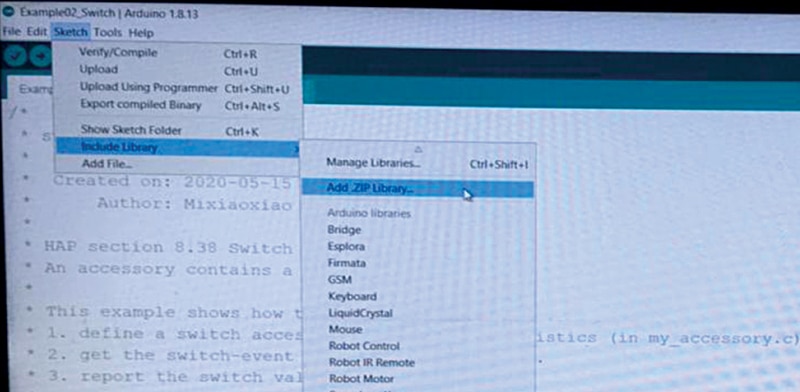
Fig. 7: Including .Zip Library to Arduino IDE - Open Example02_Switch file, as proven in Fig. 8. The unique ‘Example02_Switch.ino’ code contains just one relay module. For including a number of (4) relays, it’s essential to make some adjustments within the code, as defined within the subsequent part.

Fig. 8: Example02_Switch - In Wifi_info.h file (Fig. 9 ), point out your individual SSID and password.

Fig. 9: Setting SSID and password - First make some adjustments in ‘my_accesory.c’ code. So as to add many units, copy and paste the highlighted half in Fig.10 as many instances because the variety of units to be added within the mission.
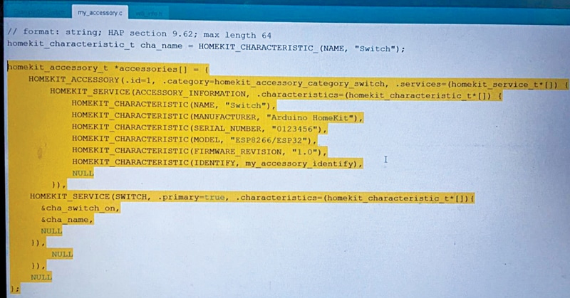
Fig. 10: The highlighted code to be copied and pasted
After including a number of instances, change the ‘id’ within the line “HOMEKIT_ACCESSORY (.id=1, .class=homekit_accessory_category_switch, .companies=(homekit_service_t*[])” as proven in Fig. 11.
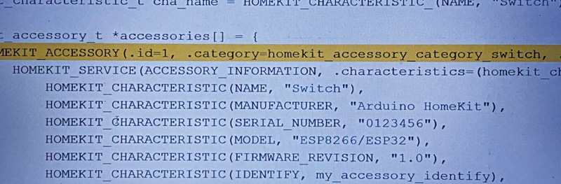
Change .id=1 to .id=2. When you have added the third system, change it to .id=3. So each time you copy and paste the highlighted half, improve the .id quantity.
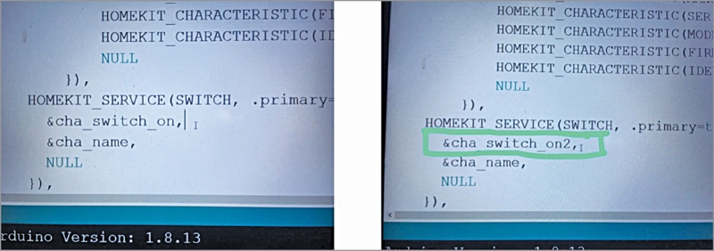
Within the highlighted half you can find “&cha_switch_on” line, as proven in Fig. 12. That is default code for channel swap quantity. When you added a brand new highlighted half, change it to “&cha_switch_on2”. It’s worthwhile to improve the swap quantity each time you add a brand new highlighted half.
Subsequent, you can find “homekit_characteristic_t cha_switch_on= HOMEKIT_CHARACTERISTIC_(ON, false);” in the identical code. Right here too, it’s essential to add this line as many instances as you’ve added the units and in addition add the switch_on quantity. For instance, in the event you added two units, the road of code can be as follows:
homekit_characteristic_t cha_switch_on = HOMEKIT_CHARACTERISTIC_(ON, false);
homekit_characteristic_t cha_switch_on2 = HOMEKIT_CHARACTERISTIC_(ON, false);
5. Now make some adjustments in Example02_Switch code. Right here, you can find the road “extern “C” homekit_characteristic_t cha_switch_on;” It’s worthwhile to add this line each time you add a tool and in addition, as earlier than, it’s important to change switch_on to switch_on2, switch_on3, and many others.
Subsequent, you can find a “#outline PIN_SWITCH 2” line of code. Copy this line and add as many instances as you’ve added new units and in addition change every pin quantity. This pin really defines the pin of NodeMCU board the place the system is linked by the relay module.
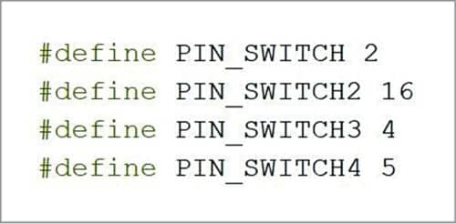
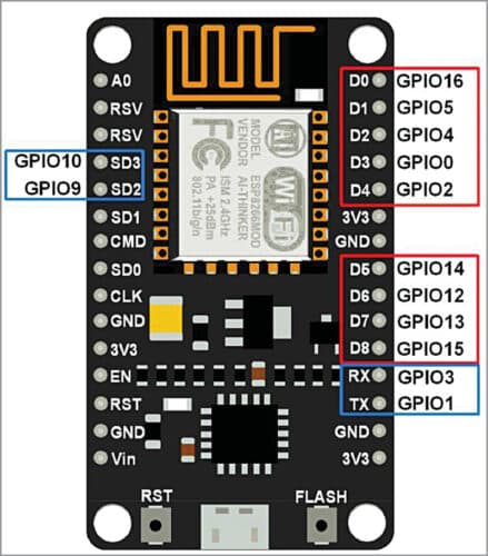
Notice that the pin 2 outlined right here isn’t the bodily pin D2 of NodeMCU; it’s GPIO pin 2. The GPIO pins are marked on NodeMCU board, as proven in Fig. 13. The GPIO pins outlined on this mission for switching the 4 relays are proven in Fig. 14.
To manage 4 home equipment, the creator used GPIO2, GPIO16, GPIO4, and GPIO5 pins of NodeMCU. Every GPIO pin needs to be linked to corresponding relay module, as proven in connection diagram of Fig. 6.
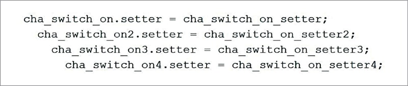
Subsequent is “cha_switch_on.setter = cha_switch_on_setter;” line of code. Copy this one too and add it as many instances because the variety of units to be added within the mission. For including 4 new units, change the switch_on and setter, as proven in Fig. 15.
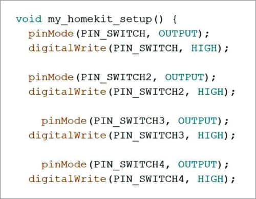
Subsequent is “void my_homekit_setup()” line. Inside that you can find “pinMode(PIN_SWITCH, OUTPUT);
digitalWrite(PIN_SWITCH, HIGH);” It’s a must to add these traces as many instances as you’ve added new units. For 4 units, it’s essential to change the variables, as proven in Fig. 16.
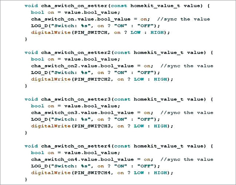
After this choose following traces:
“void cha_switch_on_setter (const homekit_value_t worth) { bool on = worth.bool_value;
cha_switch_on.worth.bool_value = on; //sync the worth LOG_D(“Swap: %s”, on ? “ON” : “OFF”);
digitalWrite(PIN_SWITCH, on ? LOW : HIGH); }”
Copy these traces and add as many instances as you’ve added new units. Then change the setter, PIN_SWITCH and cha_switch_on within the code, as proven in Fig. 17. That is mainly the .setter perform to get the switch-event despatched from Apple’s iOS system.
Now, add the code to NodeMCU board. Subsequent, arrange the Apple HomeKit app.
Organising Apple HomeKit
Observe the steps given beneath to arrange the Apple HomeKit app utilizing Apple’s iPhone SE system.
Step 1. Obtain the HomeKit from App Retailer.
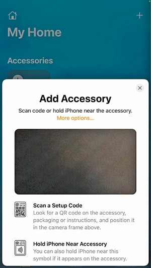
Step 2. On the highest proper nook, click on on the plus (+) button. Choose Add Accent. You will note a pop-up window, as proven in Fig. 18. Choose Extra choices… to proceed.
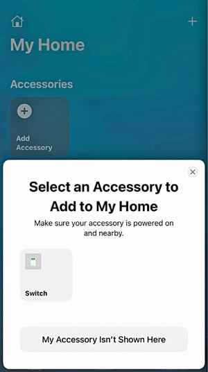
Step 3. Subsequent one other pop-up window seems, as proven in Fig. 19. Right here you can find your “Swap” system. Click on on the Swap.
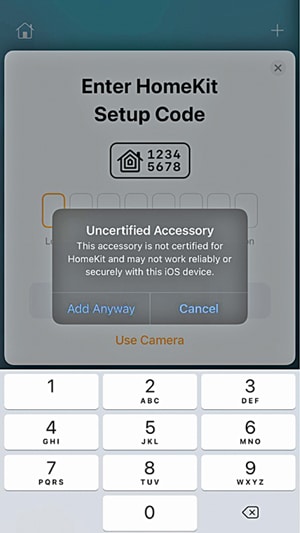
Step 4. You will note a warning message popping up. Simply click on on Add Anyway choice, as proven in Fig. 20.
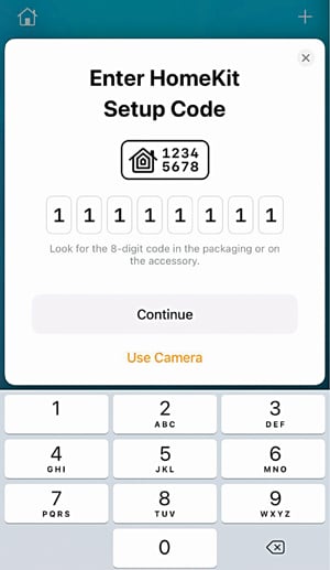
Step 5. It’s worthwhile to add 8-digit setup code. Right here, 11111111 is the default setup code, as proven in Fig. 21.
Step 6. Now it can ask for swap location. You possibly can select as per your setup. Right here Bed room swap is used. Click on Proceed to proceed with the steps.
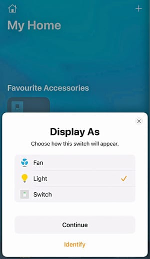
Step 7. Subsequent the Show As window pops up, as proven in Fig. 22. You possibly can select any of the units listed, together with fan or gentle, or swap, if they’re linked. Then click on Proceed.
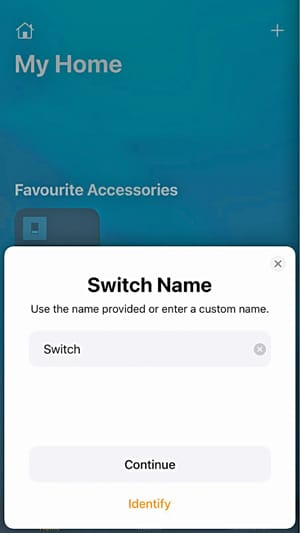
Step 8. Now it can ask for Swap title, as proven in Fig. 23. This function provides you the flexibility to set any customized title in your swap. Then click on Proceed
Step 9. Lastly, a window pops up exhibiting that swap has been added to your private home. Click on Finished.
Now you possibly can manually management all of the 4 home equipment out of your iPhone system by urgent the respective buttons or by voice instructions. The Hey Siri function allows you to management the home equipment utilizing your individual voice instructions.
For instance, to activate the bed room gentle, simply say “Hey Siri, activate the bed room gentle.” Instantly, the app will reply with voice “Okay, the swap is on” together with the textual content displayed on the app, as proven in Fig. 24. On the identical time, the bed room gentle will activate.
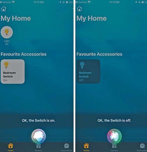
Equally, to show it off, say “Hey Siri, flip off the bed room gentle.” The app will give “Okay, the swap is off” voice response together with the textual content on the app. On the identical time, the bed room gentle can be turned off.
Equally, you possibly can management different home equipment which are already linked to NodeMCU and programmed within the app.
Notice. After importing the code to NodeMCU, in case you need to make some adjustments within the code, first be sure to erase the flash reminiscence of your NodeMCU. Then solely you possibly can add the modified code into the NodeMCU. In any other case, the app could give “Not out there” error message.
Rohan Barnwal is an electronics hobbyist and Youtuber. Rahul Barnwal, a B.Tech from Indian Institute of Info Expertise, Kottayam is a physics and electronics fanatic
Obtain supply code
Rohan Barnwal is an electronics hobbyist and Youtuber. Rahul Barnwal, a B.Tech from Indian Institute of Info Expertise, Kottayam is a physics and electronics fanatic
