What are Digital Alerts and Circuits?
Digital Alerts
A Digital Sign is a sort of Sign that has two discrete ranges, both HIGH (1) or LOW (0). These two ranges are often represented by-
- LOGIC 1 = HIGH = TRUE = ON = YES
- LOGIC = LOW = FALSE = OFF = NO
The idea of the Binary quantity system is the correct illustration of Digital Alerts. Digital Alerts work on the rules of Boolean Algebra, binary arithmetic developed by George Boolean.
Digital Circuits
Digital Alerts function at excessive speeds and drive Digital Circuits that comprise some fundamental elements corresponding to Diodes, Inductors, Capacitors, Resistors, Batteries, and Logic Gates.
There are numerous Logic households that comply with the precept of Digital Alerts. Examples of such Logic households think about 3.5V to 5V voltage as excessive logic and 0V to 1V as low logic. This implies voltage mendacity wherever between 3.5V to 5V can be represented by 1 and voltage mendacity wherever between 0V to 1V can be represented by 0. The precise worth of voltage is just not essential in digital alerts.
Illustration for a spread of voltages as 1 or 0, makes digital circuit operation less complicated than analog or fuzzy circuits. Working solely in two states, both excessive or low, makes these alerts quick, and fewer vulnerable to noise, temperature, and regardless of the ageing elements.
As in comparison with analog methods, Digital circuits comply with the ideas {of electrical} community evaluation and have a “reminiscence”.
There are two sorts of Digital Circuits: Combinational Digital circuits and Sequential Digital Circuits.
- Combinational Digital Circuits are the kind of digital circuits by which output relies upon upon inputs at that current time.
- Sequential Digital Circuits are time-dependent digital circuits by which the outputs rely upon previous states as they’ve reminiscence items.
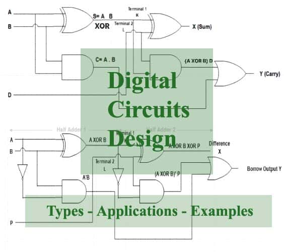
Digital Circuit Design
Digital Circuits are designed utilizing logic gates, diodes, transistors, inductors, capacitors, and resistors. As Digital Circuits comply with Boolean Legal guidelines, the logic expressions needs to be simplified for a small circuit.
Small the digital circuit, the simpler for it to be embedded in Built-in Circuits (ICs). It is because the primary aim of {hardware} methods is to scale back IC Packages.
Design Examples
-
Design a Full Adder utilizing two Half Adders
Building:
The inputs of the primary half adder are two single binary digits A and B. The output of the primary half adder sum S is fed to the enter of the second half adder terminal 1 on Okay. The sum output of the second half adder is obtained throughout X.
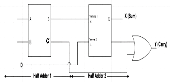
The carry bit D is instantly utilized throughout terminal 2 on L of the second half adder. The carry output is obtained throughout Y of the second half adder.
Operation
The Boolean expression for Output Sum at S of the primary half adder,
S= A ⊕ B
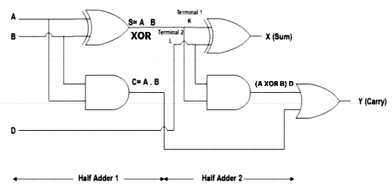
The output throughout the second half adder for Sum X is a direct XOR operation of S of the primary half adder at enter terminal 1 and the carry bit at enter terminal 2 of the second half adder
X= A ⊕ B ⊕ D
Therefore, the expression for the sum of two half adders is similar because the sum of the Full Adder circuit.
The Boolean expression for Output Carry at Y is an OR operation of the output carry of each the primary and second-half adders.
Y= (A ⊕ B) D + AB
For this, now we have to unravel the Boolean expression,
By circuit diagram,
Y= (A’B + AB’) D + AB
Y= A’BD + AB’D + AB
By inserting the Boolean Legislation of OR,
1+D= D
Y= A’BD+ AB’D + AB (1+D)
Y= A’BD+ AB’D + AB + ABD
Y= BD (A’+A) + AB’D + AB
By utilizing the Boolean Legislation of OR,
A+A’= 1
Y= BD + AB’D + AB
By inserting the Boolean Legislation of OR,
1+D= 1
Y= BD + AB’D + AB (1+D)
Y= BD + AB’D + AB + ABD
Y= BD + AD (B’+B) + AB
By utilizing the Boolean Legislation of OR,
B+B’= 1
Y= BD + AD + AB
The expression for Carry of two half adders is similar as that of a Full Adder.
Therefore, through the use of combinational digital logic, we will design a full adder utilizing two half adders.
-
Design a Full Subtractor utilizing two Half Subtractors
Building:
The inputs of the primary half subtractor are two single binary digits A and B. The output of the primary half subtractor distinction D is fed to the enter of the second half subtractor terminal 1 on Okay. The distinction output of the second half subtractor is obtained throughout X.
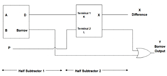
The borrow bit P is instantly utilized throughout terminal 2 on L of the second half subtractor. The borrow output is obtained throughout Y of the second half subtractor.
Operation
The Boolean expression for Output Distinction at D of the primary half Subtractor is,
D= A ⊕ B

The output throughout the second half subtractor for Distinction X is a direct XOR operation of D of the primary half subtractor at enter terminal 1 and the borrow bit P at enter terminal 2 of the second half subtractor.
X= A ⊕ B ⊕ P
Therefore, the expression for the Distinction between two half subtractors is similar because the distinction of the Full Subtractor circuit.
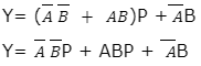
The Boolean expression for Output Borrow at Y is an OR operation of the output borrow of each the primary and second-half subtractors.
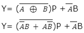
As XNOR is the complement of XOR,
By inserting the Boolean Legislation of OR,
1+P= 1
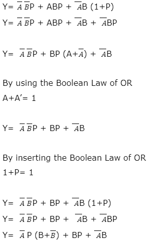
By utilizing the Boolean Legislation of OR,
B+B’= 1
![]()
The expression for Borrow Output of two half subtractors is similar to that of a Full Subtractor.
Therefore, through the use of combinational digital logic, we will design a full subtractor utilizing two half subtractors.
Digital Circuit Design Purposes
- Digital {Hardware} had tailored Digital alerts, circuits, and their logic and design ideas since 1938 and continues to work on the identical.
- Digital Programs are the important thing elements behind the operations of Computer systems, Calculators, the Web, Web Communication, and Telecommunications.
- Digital circuits and designs are utilized in
-
- Built-in Circuits (ICs)
- Programmable Logic Units (PLDs)
- Subject-programmable Gate Arrays (FPGAs)
- Digital Computer systems
- Digital Calculators
- {Hardware}
