What’s a Transformer
A transformer is a static gadget that transfers electrical energy between two alternating present circuits with no change in frequency. The Voltage of the circuit may be diminished or elevated in accordance with the present relationship. This is named stepping up (rising) the voltage and stepping it down (reducing).

The transformer is a passive gadget that works on the ideas of electromagnetic induction used on the enter to step up the voltage and step down the output voltage on the outer terminal.
Transformer Building
There are three elements of a Transformer:
- Iron Core
- Major Winding
- Secondary Winding
Core
The core of the transformer is rectangular in form and laminated. Throughout the transformer development, it must be designed in such a manner that there are fewer core losses in the course of the operation of the Transformer. Core losses and iron losses are a mix of all of the losses that occur contained in the core.
The core lets an alternating flux drive by means of it. This may trigger power loss within the core attributable to hysteresis loss. So, it’s best to select a high-quality Silicon Metal with low hysteresis loss to assemble the core of a Transformer. This metal is termed the Smooth Metal Core of the Transformer.
The alternating flux produces sure currents referred to as Eddy currents. These currents use electrical power and trigger sure losses, identified by the identify of eddy present losses of the Transformer. The core have to be manufactured as a gaggle of laminations. These successive laminations are electrically insulated to cut back eddy currents. The insulation layer is made up of Varnish, which gives excessive resistance to eddy currents.
Windings
There are two windings on the transformer i.e. Major Winding and Secondary Winding. The Major Winding is related to the enter terminal and is chargeable for producing a self-induced EMF. The Secondary Winding is related to the output load. These windings are positioned on the core and are electrically insulated from one another and the core for correct functioning and discount in losses.
These coils have totally different numbers of turns in contrast to one another. The Major Winding of the Transformer has N1 turns. Equally, the Secondary Winding of the Transformer has N2 turns. Relying upon the operation of the transformer, N1< N2, N1> N2, and N1= N2.
Kinds of Transformer Building
There are two designs of Transformers relying upon the location of the core and the coils in the course of the transformer development.
Core-type Building
The Major Winding is certain on one finish of the iron core, and the Secondary Winding is positioned on the opposite finish. Every of the coils is split into equal elements and positioned on the 2 ends of the iron core. Each the windings enclose the entire core.
Though Major and Secondary Windings are electrically insulated from one another, each of them are related in collection in core-type development.
This will increase the typical size of the core and gives magnetic coupling between each of the windings. The magnetic flux follows a steady path and generates an EMF.
The core-type transformer development is appropriate for high-voltage transformers. They’re widespread amongst each sorts of constructions and are straightforward to restore attributable to their straightforward association, in case of any injury.
Shell-type Building
The shell-type development permits the core to surrounding Major and Secondary Windings. There are three faces of the iron core- left, central, and proper face. The first and secondary coils are certain to the central face of the iron core. The core encloses each the windings and the typical size of the core is much less.
Though electrically insulated from one another, the first and secondary coils generate totally different voltages V1 and V2. This distributes magnetic flux into two elements. The shell-type development of the Transformer is appropriate for low-voltage transformers however is troublesome to restore attributable to their sophisticated association, in case of any injury.
Working Precept of a Transformer
A transformer is produced from a core that has widespread enter and output sides. Two inductive windings are embedded on this core which is electrically insulated from one another. The enter coil by which electrical voltage is fed is named Major Winding. The output coil from which {the electrical} voltage is drawn known as the Secondary Winding.
You possibly can test the detailed rationalization video of how a transformer works.
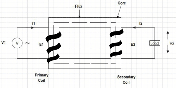
When an enter alternating voltage V1 is utilized throughout the first coil of the transformer, it generates an alternating present I1. An alternating electromotive power emf e1 is produced within the core.
Based on Faraday’s legislation of electromagnetic induction,
![]()
An electromotive power emf e1 runs by means of the first coil.
The place,
- EMF is a first-order time by-product of Electromagnetic Flux.
- e1= Electromotive Pressure
- N1= Variety of Turns in a main coil
The electromagnetic flux emf e1 is not directly equal and reverse to the enter alternating voltage V1.
If we assume that the leakage flux is negligible and there are not any losses within the transformer.
On account of Faraday’s legislation of electromagnetic induction, an Electromotive Pressure emf e2 is produced within the secondary coil.
An electromotive power emf e2 runs by means of the secondary coil.
![]()
The place,
- EMF is a first-order time by-product of Electromagnetic Flux.
- e2= Electromotive Pressure
- N2= Variety of Turns in a secondary coil
As per Faraday’s legal guidelines, the emf e1 is a self-induced electromotive power, and emf e2 is a mutually-induced electromotive power.
The power switch takes place by means of main to secondary winding with mutual induction. The secondary coil is closed by means of a load as the present I2. flows by means of the circuit.
Based mostly on the variety of turns within the main and secondary windings, we are able to design a step-up or step-down transformer.
Step-up and Step-Down Transformers
Step-up Transformer
If
N1 < N2
e1 < e2
A Step-up Transformer is outlined as a tool that receives {an electrical} alternating voltage and converts it into a better voltage. It’s the transformer that has extra turns within the secondary winding in comparison with the first coil. Used within the enter terminal of the transmission line.
Step-down Transformer
If
N1 > N2
e1 > e2
A Step-down Transformer is outlined as a tool that receives {an electrical} alternating voltage and converts it right into a decrease voltage. It’s the transformer that has extra turns within the main winding in comparison with the secondary coil. Used within the output terminal of the transmission line.
Isolation Transformer
N1 = N2
This is named the Isolation Transformer by which the variety of turns is equal within the main and secondary windings. Which means that the induced voltages and present values for main and secondary coils are equal. This type of transformer is used to offer Galvanic isolation, cut back noise, and supply safety in opposition to electrical shocks between conductors and the bottom.
Designing a Transformer
EMF Equation of a Transformer
The EMF equation of the Transformer is necessary to design a step-up or step-down configuration.
An alternating voltage that’s sinusoidal in nature is utilized as an enter throughout the first winding. Based on the operation of the transformer, the alternating voltage produces a flux within the iron core. This alternating flux varies sinusoidally throughout the transformer.
The equation of alternating flux within the iron core of the transformer
![]()
Based on Faraday’s legal guidelines of electromagnetic induction, the EMF e1 is self-induced and EMF e2 is mutually-induced.
The self-induced EMF e1 of the first winding is given by
![]()
By placing the values of equation 1 in equation 2
![]()
Differentiating with respect to t,
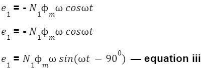
By evaluating equations i and iii, we are able to conclude the self-induced EMF e1 lags behind the electrical flux by 900.
The usual equation becomes-
![]()
The basis imply sq. RMS worth of EMF in Major Winding is given by-
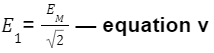
By equation iv,
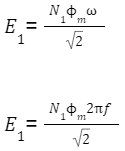
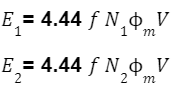
The self-induced EMF e1 in Major Winding is given by:
![]()
Equally, the mutually-induced EMF e2 in Secondary Winding is given by:
![]()
The place, f is the availability frequency, and m is the utmost flux.
These equations (Equations vi and vii) are referred to as EMF equations of the Transformer.
Flux Density (BM)
The Most Flux Density BM within the magnetic core is expressed in Tesla with the inverse relationship to the world of cross-section (A).
![]()
The coil with a extra variety of turns could have a better voltage winding, and the coil with a much less variety of turns could have a lesser voltage winding.
Transformer Ratio (Okay)
The Transformer Ratio (Okay) is a vital issue throughout transformer development in designing a step-up, and step-down transformer.
Contemplating the EMF equations of a Transformer by (Equation vi, and vii),
Dividing equation vii by equation vi,
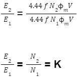
This Ratio is named the Transformer Ratio (Okay).
If we think about main and secondary voltage drop to be 0,
V1= E1 — equation viii
V2= E2 — equation ix
Dividing equation ix by equation viii
Okay = E2/E1 = V2/V1
If we think about the transformer losses to be 0,
V1I1= V2I2 — equation x
Rearranging equation x,
Okay = I1/I2 = V2/V1
The Transformer Ratio Formulation turns into
Okay = N2/N1 = E2/E1 = V2/V1 = I1/I2
For Designing
Step-up Transformers,
N1 < N2
Okay > 1
Step-down Transformers,
N1 > N2
Okay < 1
Isolation Transformers,
N1 = N2
Okay = 1
Splendid and Sensible Transformers
Splendid Transformer
A great Transformer is a theoretical transformer by which there are not any losses. The transformer which has been described above is a perfect transformer by which no core losses happen on both facet of the transmission line. However in real-time methods, a great transformer doesn’t exist. As an alternative, a sensible transformer with losses is present in use.
Sensible Transformer
In a Sensible Transformer, the Major, and Secondary Windings usually are not best as they’ve a small-value resistance. It’s accountable to trigger some energy loss within the windings, this loss is named Copper Loss.
The alternating flux produces sure currents contained in the transformer, these are referred to as eddy currents. Eddy present loss and hysteresis loss mix to make Core Loss. Furthermore, it has been noticed that there’s a leakage in electrical flux close to the windings.
Splendid Transformer vs Sensible Transformer
The Core, and Copper Losses of the Transformer with every other leakages as such make up a Sensible Transformer. The voltage regulation of the Sensible Transformer is rarely 0%, and effectivity ranges between 93-97%.
Whereas within the Splendid Transformer, there isn’t a resistance of Major, and Secondary Windings. The absence of resistance causes no voltage drop or energy loss. There is no such thing as a leakage of electrical flux close to the windings in a great transformer. Moreover, there are not any eddy currents produced by the windings and no hysteresis losses.
Therefore, an Splendid Transformer has no Copper, and Core Losses with no Electrical Flux leakage. The voltage regulation of the Splendid Transformer is 0%, and effectivity is 100%. However that is inconceivable to assemble and exists in hypothetical experiments.
Makes use of of Transformers
Enter and Output of a transmission line
In a standard energy system, you possibly can discover that the enter voltage is usually 11kV/22 kV. It’s handed by means of the step-up transformer to generate a voltage degree of 220kV/400 kV.

Excessive voltage to run a circuit or switch between two methods will increase effectivity and reduces line losses. When the circuit performs its operation, you could find that the output of the standard energy system makes use of a step-down transformer. On the finish of the transmission line, the working voltage is once more diminished to 11 kV/22 kV.
Energy Distribution
On the time of Energy Distribution, transformers convert a line voltage of 400 V to a part voltage of 230 V.
Energy Loss Lower
The transformer transmits the identical quantity of Energy however will increase the voltage degree. This decreases the present flowing by means of the circuit. The decreased present circulation causes the facility losses Loss=I2R to lower within the transmission line.
In case you have any doubts or questions, please be happy to ask within the remark part under.
