 Telephones are getting smarter and extra complicated with many features that almost all of us discover tough to make use of. The trendy smartphone makes use of both a backlight show or an OLED show that may hurt our eyes on extended use.
You could have puzzled how telephones are designed and whether or not you possibly can make your individual smartphone. So, right here is how one can make your individual smartphone having spectacular E-ink expertise. This full-touch, finger-sized cellphone makes use of UI-powered Linux working system (OS) that may be accessed utilizing any OS and VNC HDMI. It could actually carry out all the fundamental features of a cellphone.
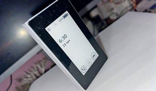
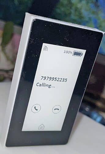
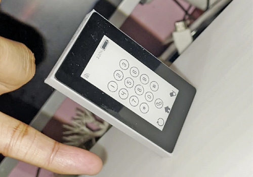
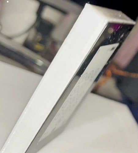
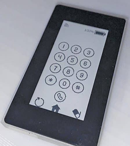
The writer’s prototype is proven in Fig. 1 and the prototype with its calling display screen is proven in Fig. 2. It’s so small (see Fig. 3) that it may be strapped to your little finger.
E-ink expertise saves energy because of the absence of a backlit shows and is sweet for individuals who need to keep away from the glare of OLED and backlit shows. E-Ink show, just like the printed paper, stays seen even when energy is lower off till you refresh it.
Nevertheless, this isn’t all. We’re going to develop the E-Ink cellphone, and, with none additional value, you’ll get a full Linux-based moveable finger-sized pc as nicely! So, allow us to begin gathering the required parts, that are listed within the desk above.
Designing
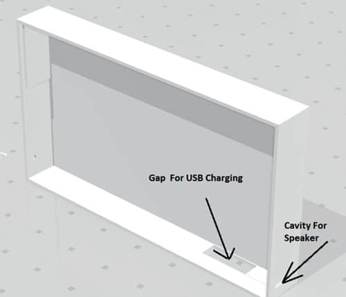
Although it’s a completely do-it-yourself DIY cellphone, we are able to design it to look slim and enticing. So, for the cellphone, make its physique the identical dimension because the E-ink contact show. Then make house, as proven in Fig. 4, for embedding the GSM module contained in the cellphone physique.
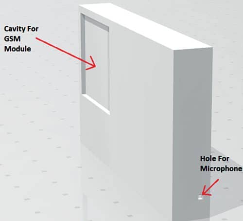
Subsequent make a tiny gap the place the speaker is to be positioned, so as to hear the sound (see Fig. 5). Equally, make holes for the mic and energy enter. Now, after designing the cellphone physique, 3D print it.
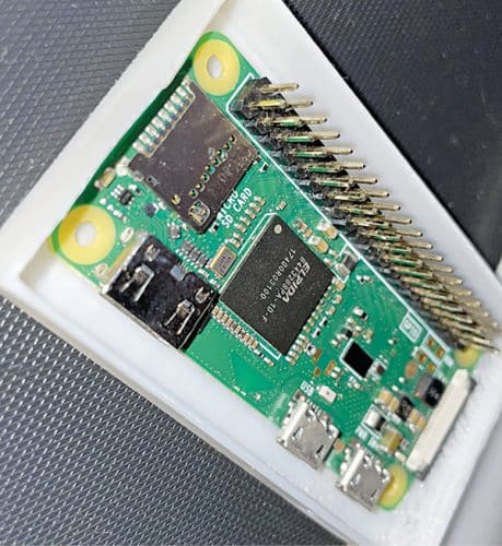
Put together the Raspberry Pi with its newest OS after which allow the SPI and I2C and serial ports of the Raspberry Pi. To do this, run the next command in Llinux terminal and allow software program configuration one after the other, as proven in Fig. 6.
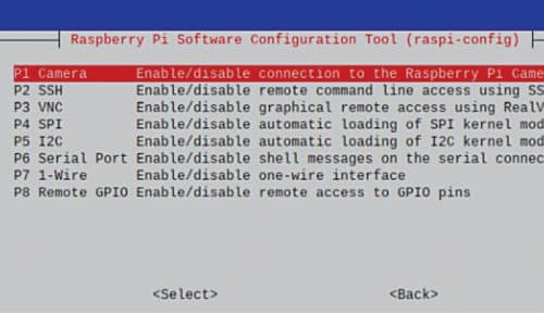
sudo raspi-config
Subsequent, set up the driving force for the E-ink contact show and the Python modules to make use of the show. To do this, open the Linux terminal and run the next instructions:
wget http://www.airspayce.com/mikem/
bcm2835/bcm2835-1.68.tar.gz
tar zxvf bcm2835-1.68.tar.gz
cd bcm2835-1.68/
sudo ./configure && sudo make && sudo make
verify && sudo make set up
sudo apt-get set up wiringpi
#For Pi 4, you must replace it:
wget https://project-downloads.drogon.
internet/wiringpi-latest.deb
sudo dpkg -i wiringpi-latest.deb
gpio -v
#You’ll get 2.52 data in the event you
set up it appropriately
sudo apt-get replace
sudo apt-get set up python3-pip
sudo apt-get set up python3-pil
sudo apt-get set up python3-numpy
sudo pip3 set up RPi.GPIO
sudo pip3 set up spidev
cd ~
git clone https://github.com/waveshare/
Touch_e-Paper_HAT
Creating UI
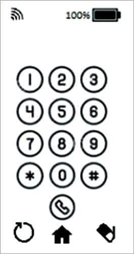
We have to create the person interface (UI) for the cellphone in order that it appears to be like lovely. You possibly can select any icon and design a customized UI of your alternative. For the prototype, spherical icons had been used, as proven in Fig. 7. For UI, we will need to have the fundamental design to carry out the fundamental features. So, right here is the record of UI pages for the fundamental cellphone features:
- Principal display screen
- Dialing display screen
- Contacts display screen
- Messages
- Incoming name
- Calling display screen
For each display screen UI, we have to get the icon, resize, and place it such that it matches contained in the precise dimension of the cellphone’s show (5.4cm dimension in prototype). For the principle display screen UI, the battery icon is used for getting energy data, a tour icon for getting the sign information, and a dial icon for the dialing display screen, contacts, and messaging screens. Within the center, it’s stored clean to show time, date, and so forth.

Create the dialing display screen UI for the numbers and different icons. Dial a quantity and go to dwelling display screen, or erase and refresh the display screen. Equally, make UIs for the remaining cellphone features and display screen.
Save the photographs from the UIs within the pic folder of the Python library that was cloned earlier. Open the code for displaying.
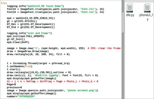
Coding cellphone OS
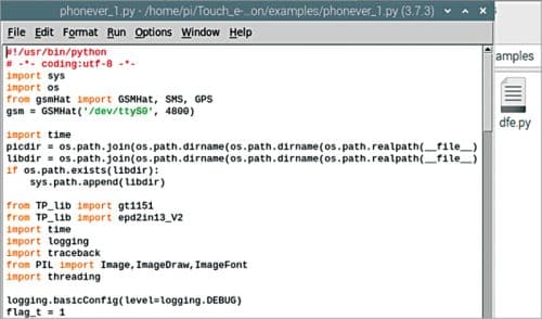
To create the code for OS for the cellphone, import the modules and library for interfacing the E-ink contact show. Then import the Python modules for utilizing the SIM 800L GSM module. Subsequent, set the trail the place you retain the UI photographs for the cellphone and create the whereas loop to verify the display screen. The web page to show is just like the earlier, however new if its earlier one has a brand new web page quantity. Replace the show with UI pic.
For the (first) dwelling web page, verify the contact factors for the icons like dial icon, contact icon, or message icon. Additionally, verify the incoming name by checking the ring pin. Then create an ‘if’ situation the place you verify the contact factors to match the vary of icons on the UI. In case you contact the cellphone icon, the contact level ought to match with the contact level akin to the cellphone.
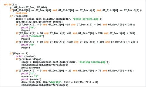
Set the perform within the if situation to vary the web page quantity to subsequent (No. 2). That’s, within the UI picture of the dialing display screen, replace the cellphone display screen and set the web page quantity to 2. Now the cellphone strikes to dial display screen with buttons numbers. Create the if situations for checking the numbers and icons.
Contact the dial pad display screen if the contact level vary of the quantity is one or two, or different quantity buttons. Replace an empty string named quantity, and add that quantity to the string. If the contact level matches with the decision icon, it sends the command to the GSM module to name that quantity. It additionally units the web page quantity to the calling display screen and updates the show with the calling display screen.
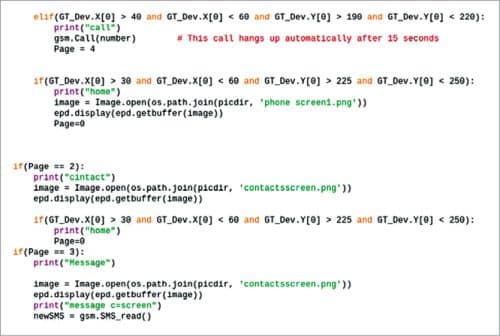
On the calling display screen, verify the contact factors for the Name Cling icon. In case your contact level matches the vary of the call-hang icon, the contact level will ship the command to SIM800L GSM module to chop the decision and hold up. It can additionally change the web page quantity to 0 and replace the show with the house display screen UI.
Equally, verify the contact factors and incoming name after which change the web page quantity and replace the show display screen with UI for the message, contact, or ringing display screen. Then in that display screen, verify the contact level for the button icon, contact level vary, and set the perform for these buttons—like hanging cellphone, dwelling, principal display screen, calling, and different features for the button icons. The Python code for attaining the above-mentioned actions are proven in Fig. 9 by means of Fig. 12.
Connection
After coding, join the parts as per the diagram proven in Fig. 13. Place the Raspberry Pi and SIM 800L module inside within the enclosure/physique that has been designed. Repair the speaker and microphone in opposition to the holes made within the enclosure for them.

Repair the battery and charging unit in between the show and Raspberry Pi. Then mount the show on the enclosure with the pins matching the E-ink feminine header-to-header on Raspberry Pi, as proven in Fig. 14. Repair the GSM module on the slot, as proven in Fig. 15, and the cellphone display screen on the bottom cellphone cowl, as proven in Fig. 16.
Testing
The E-ink cellphone is now prepared to indicate its magic. Insert the SIM in GSM module and run the OS code, and you’re prepared to make use of it.

Faucet on on the Name icon and also you get the dialing display screen. Key in a cellphone quantity and contact on Name icon to make the decision. Contact the Residence icon to get the house display screen and contact Contacts to see the contact numbers.
Subsequent, strive making a name from another cellphone to your E-ink cellphone. When related, the buzzer begins ringing and it takes you to the ringing display screen. Right here, contact the Name Attend icon to attend the decision and Name Cling icon to hold up the decision.
The ultimate assembled E-ink cellphone is proven in Fig. 17. Take pleasure in!
Ashwini Kumar Sinha is a expertise fanatic at EFY
